Reconfigurable optical mode converter

A converter, light mode technology, used in light guides, optics, instruments, etc.

Active Publication Date: 2018-09-11
LANZHOU UNIVERSITY
View PDF6 Cites 10 Cited by
  • Summary
  • Abstract
  • Description
  • Claims
  • Application Information

AI Technical Summary

Problems solved by technology

[0007] The purpose of the present invention is to provide a reconfigurable optical mode converter to solve the problem of free conversion between different waveguide modes in the optical communication mode multiplexing technology, and on this basis to provide a scalable optica

Method used


Image

  • Reconfigurable optical mode converter
  • Reconfigurable optical mode converter
  • Reconfigurable optical mode converter

Examples


Embodiment Construction

[0030] The present invention will be described in detail below in conjunction with the accompanying drawings and specific embodiments.

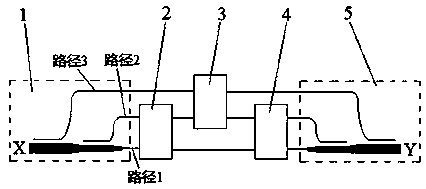
[0031] Such as figure 1 As shown, the optical mode converter of the present invention includes a first device 1, a first optical switch 2, a second optical switch 3, a third optical switch 4 and a second device 5 connected in sequence; the second optical switch 3 is also respectively It is connected with the first device 1 and the second device 5 , and the first optical switch 2 is connected with the third optical switch 4 .

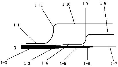
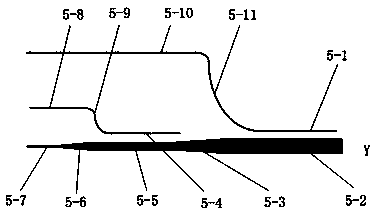
[0032] Both the first device 1 and the second device 5 employ a mode multiplexer / demultiplexer. The mode multiplexer / demultiplexer can be realized by structures such as directional coupler, microring resonator, Y branch, grating coupler, etc. Here, the mode multiplexer / demultiplexer based on the directional coupler is taken as an example for illustration.

[0033] Such as figure 2As shown, the first device 1 in the ...


PUM


Abstract

The invention relates to a reconfigurable optical mode converter. The reconfigurable optical mode converter comprises a first device, a first optical switch, a second optical switch, a third optical switch and a second device which are connected with one another sequentially; the second optical switch is connected with the first device and the second device; the first optical switch is connected with the third optical switch; and mode multiplexing/demultiplexing devices are adopted as the first device and the second device. According to the invention, a relatively simple principle in a traditional wavelength division multiplexing technology is applied to a mode multiplexing technology, so that the reconfigurable optical mode converter can be realized, and free conversion between differentwaveguide modes can be realized. On the basis of the same structure, an extensible mode selection exchanger is provided, and therefore, data selective exchange between any two modes can be realized, and problems such as flexible data network switching and data flow guide in an optical communication mode multiplexing technology can be solved, and the extensible mode selection exchanger is expectedto play an important role in implementing a flexible mode multiplexing optical communication network.

Description

technical field [0001] The invention belongs to the technical field of optical mode multiplexing, and relates to a reconfigurable optical mode converter. Background technique [0002] With the development of the information age, people's requirements for large-capacity and high-speed communications are getting higher and higher. In order to meet the growing demand, many multiplexing technologies in high-speed optical transmission have been researched, such as time division multiplexing technology, code division multiplexing technology, wavelength division multiplexing technology, space division multiplexing technology, polarization multiplexing technology, Mode multiplexing technology, etc. Among them, wavelength division multiplexing, especially dense wavelength division multiplexing technology has been widely used in modern optical fiber communication technology. However, the demand for communication capacity and communication rate is increasing day by day, and the numbe...

Claims


Application Information

Patent Timeline
IPC IPC(8): G02B6/14G02B6/293
CPCG02B6/14G02B6/29338
Inventor 田永辉韩旭肖恢芙刘子龙陈文平赵婷廖苗苗
Owner LANZHOU UNIVERSITY
Why Eureka
Try Eureka