Optimized configuration method of transformer neutral point capacitor direct-current blocking device

A technology of transformer neutral point and DC blocking device, applied in emergency protection circuit devices, electrical components, etc., can solve the problem of difficult to obtain the optimal configuration scheme of capacitor DC blocking device, inaccurate calculation of transformer neutral point DC current, and algorithm It is easy to fall into problems such as local convergence, so as to achieve the effect of improving particle update quality and algorithm calculation efficiency, increasing general applicability, and improving convergence speed and calculation accuracy.

Active Publication Date: 2018-09-11
SICHUAN UNIV
View PDF0 Cites 12 Cited by
  • Summary
  • Abstract
  • Description
  • Claims
  • Application Information

AI Technical Summary

Problems solved by technology

[0004] For the problem of optimal configuration of capacitor DC blocking devices, the existing methods mostly use optimization algorithms such as genetic algorithm to solve the problem, but there are problems such as inaccurate calculation of DC current at the neutral point of the transformer, and the algorithm tends to fall into local convergence, and it is difficult to obtain the capacitance Optimal Configuration Scheme of DC Blocking Device

Method used


Image

  • Optimized configuration method of transformer neutral point capacitor direct-current blocking device
  • Optimized configuration method of transformer neutral point capacitor direct-current blocking device
  • Optimized configuration method of transformer neutral point capacitor direct-current blocking device

Examples


Embodiment

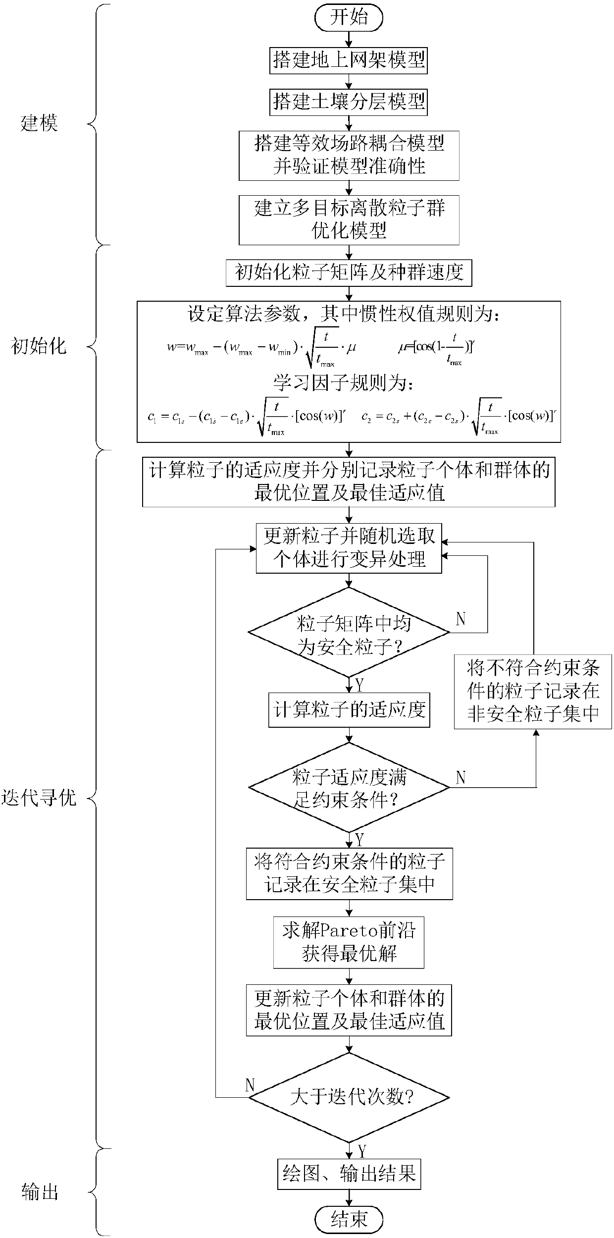
[0045]This embodiment takes a DC grounding pole as an example to build an equivalent field-circuit coupling model, calculate the DC current value at the neutral point of each transformer in the power grid by using the finite element method, and use the multi-objective discrete particle swarm optimization algorithm to optimize the capacitor DC blocking device Configuration, from a global point of view to suppress the DC bias phenomenon of the transformer, the flow chart of the optimal configuration method of the capacitor DC blocking device is as follows figure 1 shown.

[0046] 1. A grid model of a DC grounded extremely near area

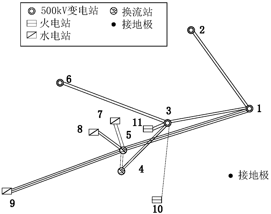
[0047] A DC grounded extremely near-area power grid includes 3 500kV power plants, 6 500kV substations, 2 DC converter stations, and 2 ±800kV UHV DC transmission channels, with transmission powers of 6400MW and 8000MW respectively. The above-mentioned power stations are numbered 1-11 in turn, and the schematic diagram of the power grid structure is...


PUM


Abstract

The invention discloses an optimized configuration method of a transformer neutral point capacitor direct-current blocking device. According to the optimized configuration method of the invention, onthe basis of an equivalent field-circuit coupling model, a finite element method is used to calculate the direct-current value of the neutral point of a grounding transformer in a power grid, and therefore, a calculation result is accurate and is close to a measured value; a multi-objective discrete particle swarm optimization algorithm is adopted, and the particle swarm optimization algorithm isimproved with nonlinear reduction inertia weight considering a cosine adjustment coefficient, and therefore, the convergence speed and calculation accuracy of the algorithm can be improved; the inertia weight and adjustment factor are adopted to control the learning factors of the multi-objective discrete particle swarm optimization algorithm, and therefore, the global search capability and localdevelopment capability of particles can be balanced; and a particle update strategy is introduced into the particle swarm optimization algorithm, and therefore, particle update quality and algorithm computational efficiency can be improved. According to the method, the capacitor direct-current blocking device is optimally configured from a global perspective, and therefore, the cost of controllingdirect-current magnetic bias can be reduced, and a control effect is obvious. The optimization algorithm has high calculation precision and high convergence speed, and is suitable for solving practical problems.

Description

technical field [0001] The invention belongs to the field of high-voltage direct current transmission, and in particular relates to an optimal configuration method of a neutral point capacitive direct blocking device of a transformer. Background technique [0002] High-voltage direct current (HVDC) technology has been widely used in my country, but when it operates in a single-pole ground loop or asymmetrical operation, the ground current is injected into the ground through the ground electrode, which changes the earth potential distribution, which may As a result, transformers with neutral points grounded will have different degrees of DC bias phenomenon, which will increase the temperature of the transformer, increase the loss, and aggravate the vibration, which seriously threatens the safe and stable operation of the power system. [0003] Installing a capacitive DC blocking device at the neutral point of the grounding transformer can completely block the DC current at the...

Claims


Application Information

Patent Timeline
IPC IPC(8): H02H7/04
CPCH02H7/04
Inventor 王渝红宋雨妍刘天宇李瑾张文韬
Owner SICHUAN UNIV
Why Eureka
Try Eureka