Corrugated film and manufacturing method thereof

A manufacturing method and a corrugated membrane technology are applied to the corrugated membrane and the manufacturing field thereof, which can solve the problems of consuming a lot of manpower and material resources, prone to wire breakage, and high energy consumption for aeration, and achieve an environmentally friendly processing and manufacturing method, a simple processing and manufacturing method, and a high working efficiency. pressure wide effect

Active Publication Date: 2020-08-11
BEIJING ORIGIN WATER FILM TECH
View PDF7 Cites 0 Cited by
  • Summary
  • Abstract
  • Description
  • Claims
  • Application Information

AI Technical Summary

Problems solved by technology

[0005] Existing flat membranes usually require frame support, the frame structure is relatively thick, and the packing density of the assembly is small, resulting in a large footprint, and a large amount of aeration is required for high energy consumption during operation
[0006] The filling density of the existing hollow fiber membrane is significantly higher than that of the flat membrane, but it is easy to be entangled by hair during operation, the roots are seriously accumulated, and broken wires are prone to occur, and offline cleaning is required after long-term operation, which consumes a lot of manpower and material resources

Method used


Image

  • Corrugated film and manufacturing method thereof
  • Corrugated film and manufacturing method thereof

Examples


Embodiment 1

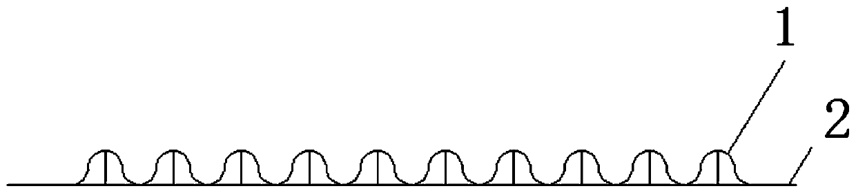
[0031] figure 1 A schematic structural diagram of the corrugated membrane provided in Embodiment 1 of the present invention; as figure 1 As shown, in the corrugated membrane provided in the first embodiment of the present invention, a support structure 2 is provided inside the corrugated membrane 1 .

[0032] Specifically, the support structure 2 is a support member disposed inside the corrugated membrane 1 .

[0033] Specifically, the support is a T-shaped support.

[0034] In the present application, the support structure 2 is provided inside the corrugated membrane 1, which greatly improves the compression resistance performance of the corrugated membrane 1, so that the applicable working pressure of the corrugated membrane 1 is wider.

[0035] It should be noted that, the support member in this embodiment is a T-shaped support member only for illustration, and other support members may also be used, which will not be repeated here.

Embodiment 2

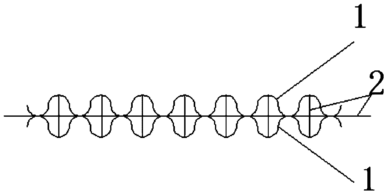
[0037] figure 2 A schematic structural diagram of the corrugated membrane provided in Embodiment 2 of the present invention; as figure 2 As shown, in the corrugated membrane provided in the second embodiment of the present invention, a support structure 2 is provided inside the corrugated membrane 1 .

[0038] Specifically, the support structure 2 is a support member disposed inside the corrugated membrane 1 .

[0039] Specifically, the support is a cross-shaped support.

[0040] In the present application, the support structure 2 is provided inside the corrugated membrane 1, which greatly improves the compression resistance performance of the corrugated membrane 1, so that the applicable working pressure of the corrugated membrane 1 is wider.

[0041] It should be noted that, the supporting member in this embodiment is a cross-shaped supporting member only for illustration, and other supporting members may also be used, which will not be repeated here.

Embodiment 3

[0043] The corrugated film provided in the third embodiment is a further improvement of the corrugated film provided in the first embodiment. figure 1 On the basis of the corrugated membrane provided in the third embodiment, a support structure 2 is provided inside the corrugated membrane 1 .

[0044] Specifically, the support structure 2 is a support member disposed inside the corrugated membrane 1 .

[0045] Specifically, the support is a T-shaped support.

[0046] In the present application, the support structure 2 is provided inside the corrugated membrane 1, which greatly improves the compression resistance performance of the corrugated membrane 1, so that the applicable working pressure of the corrugated membrane 1 is wider.

[0047] It should be noted that, the support member in this embodiment is a T-shaped support member only for illustration, and other support members may also be used, which will not be repeated here.

[0048] Specifically, the corrugated shape of ...


PUM


Abstract

The invention discloses a corrugated film. A support structure is arranged in the corrugated film. The corrugated film has the advantages that through the support structure in the corrugated film, compressive property of the corrugated film is improved greatly, and the applicable working pressure of the corrugated film is increased. The invention further provides a manufacture method of the corrugated film. The manufacture method includes preparing a composite film, performing hot extrusion on the prepared composite film to form corrugation, and performing press fit on the composite film and the support structure to acquire the corrugated film. A brand-new corrugated-film manufacture method is provided besides coating-based film formation methods, and can be applied to corrugated films which cannot be easily dissolved by solvents and cannot be processed by coating methods. The manufacture method has the advantages that the manufacture method is simpler than the prior art, chemical rawmaterial preparation steps, coating steps and coagulation bath are omitted, water is saved, environmental protection is achieved, and pollutants are avoided.

Description

technical field [0001] The invention relates to the technical field of sewage treatment, in particular to a corrugated membrane and a manufacturing method thereof. Background technique [0002] Membrane Bioreactor Membrance Bioreactor, MBR is a biochemical reaction system that integrates membrane separation technology and biodegradation of bioreactors. [0003] Membrane separation technology is a commonly used physical treatment technology in the field of sewage treatment. [0004] There are two main structural forms of membranes usually selected for MBR: hollow fiber membranes and flat membranes. [0005] The existing flat membrane usually needs frame support, the frame structure is thick, and the packing density of the group device is low, which leads to a large floor area, and requires a large amount of aeration and high energy consumption during operation. [0006] The filling density of the existing hollow fiber membrane is significantly higher than that of the flat m...

Claims


Application Information

Patent Timeline
Patent Type & Authority Patents(China)
IPC IPC(8): B01D69/10B01D69/12
CPCB01D69/10B01D69/12B01D2311/2688B01D2325/00
Inventor 陈亦力徐航丑树人代攀
Owner BEIJING ORIGIN WATER FILM TECH
Why Eureka
Try Eureka