A system and application method for in-situ remediation of polluted soil
A technology for polluted soil and in-situ remediation, which is applied in the field of systems for in-situ remediation of contaminated soil, can solve the problems of reduced leaching efficiency, affecting the popularization and application of shaft leaching technology, and achieves improved suction efficiency and is conducive to large-scale implementation. The effect of leaching, which is beneficial to the promotion and application
- Summary
- Abstract
- Description
- Claims
- Application Information
AI Technical Summary
Problems solved by technology
Method used
Image

Examples
Embodiment 1
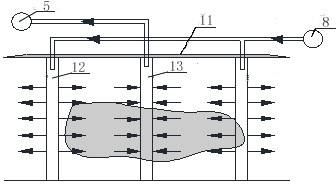
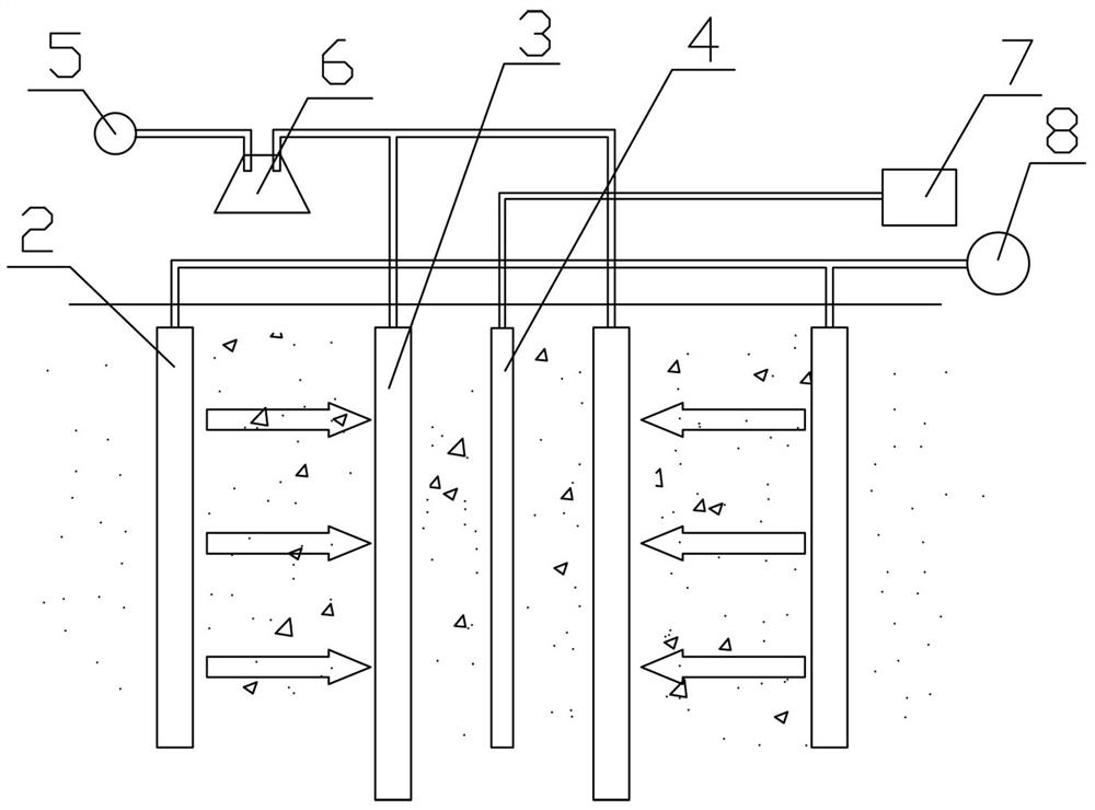
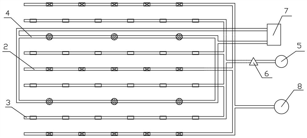
[0033] Such as figure 2 , Figure 4 , Figure 5 Shown: a system for in-situ remediation of contaminated soil, including a freezer 7, a liquid injection pump 8, a vacuum pump 5, a steam-water separator 6, several temperature sensors and a freeze-thaw rinsing unit, a freeze-thaw leaching unit The washing unit includes two liquid injection drainage plates 2, two liquid extraction drainage plates 3 and a freezing pipe 4, and the two liquid extraction drainage plates 3 are symmetrically arranged on the outside of the freezing pipe 4 with the freezing pipe 4 as the center. The liquid injection and drainage plate 2 described above is symmetrically arranged on the outside of the liquid suction and drainage plate 3 with the freezing pipe 4 as the center, and the temperature sensors are arranged at equal intervals between the freezing pipe 4 and the liquid injection and drainage plate 2; the refrigerator 7 passes through the pipeline Connect to the freezing tube 4, the freezing tube ...
Embodiment 2
[0042] Such as Figure 2 to Figure 4 As shown, a system for in-situ remediation of contaminated soil includes a freezer 7, a liquid injection pump 8, a vacuum pump 5, a steam-water separator 6, several temperature sensors and two freeze-thaw rinsing units, one freeze-thaw The rinsing unit includes two liquid injection drainage plates 2, two liquid suction drainage plates 3 and a freezing pipe 4, and the two liquid suction drainage plates 3 are symmetrically arranged on the outside of the freezing pipe 4 with the freezing pipe 4 as the center. The liquid injection drainage plate 2 is symmetrically arranged on the outside of the liquid suction drainage plate 3 with the freezing pipe 4 as the center, and the temperature sensors are arranged at equal intervals between the freezing pipe 4 and the liquid injection drainage plate 2; The units are arranged in series, and the two freeze-thaw rinsing units in series share a liquid injection and drainage plate 2. The refrigerator 7 is co...
PUM
 Abstract
Description
Claims
Application Information