Welding operation platform for industrial robot

A welding workbench, industrial robot technology, applied in workbenches, welding equipment, auxiliary welding equipment, etc., can solve the problems of the welding workbench having no installation platform, the welding workbench being inconvenient to move, affecting the welding accuracy, etc., and achieving simple and convenient portability. , broad application prospects and practical advantages, easy to use and flexible effects

Inactive Publication Date: 2018-09-14
SUZHOU LONGQI AUTOMATION TECH CO LTD
1 Cites 1 Cited by

AI-Extracted Technical Summary

Problems solved by technology

[0004] However, after analysis, it is found that the existing welding workbench has a complicated structural design, and it is difficult to operate during the welding operation, which is not convenient for the welding work. Moreover, the existing welding workbench does not have a mounting platform, and the industrial robot needs to use an...

Method used

Further, described spring shock absorber 14 inside is provided with shock-absorbing spring 16, and described shock-absorbing spring 16 bottom is provided with spring shock-absorbing layer 17, and described shock-damping spring 16 and spring shock-absorbing layer 17 can reduce shock , Improve the accuracy of welding work.
Principle of work: at first, industrial robot is installed on the mounting table 6, and it is fixed, then external circuit is connected, then the workpiece that needs to be welded is placed in T-shaped groove 9, and uses compression shaft 12 Fix it, then tighten the adjusting nut 13, fix the pressing shaft 12, avoid welding errors caused by workpiece movement during welding, because the bottom...

Abstract

The invention discloses a welding operation platform for an industrial robot. The welding operation platform comprises a working table. A mounting table is arranged at one end of the top of the working table, and the mounting table is arranged on the working table in a covering mode and fixedly connected with the working table through bolts. Locking holes are formed in the side top of the mountingtable, and mounting connectors are formed in the top of the mounting table. The mounting connectors are formed in the mounting table in an embedded mode and tightly attached and fixed to the mountingtable. T-shaped grooves are formed in one side of the mounting table. According to the welding operation platform for the industrial robot, the structure is compact and stable, protective measures are comprehensive, using is convenient and flexible, operating is safe and reliable, the stability is high, abrasive resistance is high, and damage is not prone to occurring; and additionally, the welding operation platform is easy and convenient to use and carry, diversified in function, convenient to mount and dismount, rapid in mounting and dismounting, small in casting cost and convenient to use, and has wide application prospects and practical advantages.

Application Domain

Welding/cutting auxillary devicesAuxillary welding devices +3

Technology Topic

EngineeringIndustrial robot

Image

  • Welding operation platform for industrial robot
  • Welding operation platform for industrial robot

Examples

  • Experimental program(1)

Example Embodiment

[0017] The following will clearly and completely describe the technical solutions in the embodiments of the present invention with reference to the accompanying drawings in the embodiments of the present invention. Obviously, the described embodiments are only some, not all, embodiments of the present invention. Based on the embodiments of the present invention, all other embodiments obtained by persons of ordinary skill in the art without making creative efforts belong to the protection scope of the present invention.
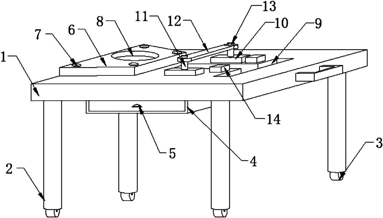
[0018] see Figure 1-2 , the present invention provides a technical solution: an industrial robot welding workbench, including a workbench 1, one end of the top of the workbench 1 is provided with an installation platform 6, and the installation platform 6 is covered and arranged on the workbench 1 , and is fixedly connected with the workbench 1 by bolts, the top of the installation platform 6 is provided with a locking hole 7, the top of the installation platform 6 is provided with an installation interface 8, and the installation interface 8 is embedded in the installation In the platform 6, and closely fit and fixed with the installation platform 6, a T-shaped slot 9 is provided on one side of the installation platform 6, and a compression shaft fixing seat 10 is provided at both ends of the side of the T-shaped slot 9, The pressing shaft fixing seat 10 is covered and arranged on the worktable 1, and is fixedly connected with the working table 1 by bolts. The top of the pressing shaft fixing seat 10 is provided with a screw rod 11, and the screw rod 11 is embedded. In the pressing shaft fixing seat 10, and closely fit and fixed with the pressing shaft fixing seat 10, a pressing shaft 12 is arranged on the top of the pressing shaft fixing seat 10, and the pressing shaft 12 is nested It is arranged on the screw rod 11 and is flexibly connected with the screw rod 11 . A spring shock absorber 14 is provided on the side of the pressing shaft fixing seat 10 .
[0019] Further, the bottom of the workbench 1 is provided with a pillar 2, and the bottom of the pillar 2 is equipped with a universal wheel 3, and the universal wheel 3 is movably connected with the pillar 2 through bolts, and through the universal wheel 3, The workbench can be moved flexibly.
[0020] Further, the bottom of the workbench 1 is provided with a storage drawer 4, and the side of the storage drawer 4 is provided with a drawer handle 5, and the drawer handle 5 is fixedly connected with the storage drawer 4 by bolts, and the storage Drawers are able to store tools and materials used for welding.
[0021] Further, an adjusting nut 13 is provided on the top of the screw 11, and the adjusting nut 13 is nested on the screw 11 and is movably connected with the screw 11. Through the adjusting nut 13, the user can adjust the pressure. The height of the tight shaft 12.
[0022] Further, a rubber pad 15 is provided inside the spring shock absorber 14 , and the rubber pad 15 is glued to the spring shock absorber 14 by glue, and the rubber pad 15 can protect the shock absorber spring 16 .
[0023] Further, the inside of the spring shock absorber 14 is provided with a shock-absorbing spring 16, and the bottom of the shock-absorbing spring 16 is provided with a spring shock-absorbing layer 17, and the shock-absorbing spring 16 and the spring shock-absorbing layer 17 can reduce vibration and improve welding performance. The precision of the work.
[0024] Working principle: First, install the industrial robot on the installation platform 6 and fix it, then connect the external wiring, then place the workpiece to be welded in the T-shaped slot 9, and fix it with the pressing shaft 12 , and then tighten the adjusting nut 13 to fix the pressing shaft 12 to avoid welding errors caused by workpiece movement during welding. Because a storage drawer 4 is provided at the bottom of the workbench 1, the welding workbench can hold the parts used for welding and tools are stored in the storage drawer 4 for easy access, and maintenance tools can also be placed in the storage drawer 4, which is conducive to the maintenance of the workbench, simplifies the process, and improves efficiency, because there is a Universal wheel 3, so this welding workbench can move flexibly, use more conveniently, can adjust the position of this workbench according to the actual situation, practicality is stronger, the damping spring 16 that is arranged in spring shock absorber 14 And spring shock-absorbing layer 17 can reduce vibration, improve the precision of welding work.
[0025] Although the embodiments of the present invention have been shown and described, those skilled in the art can understand that various changes, modifications and substitutions can be made to these embodiments without departing from the principle and spirit of the present invention. and modifications, the scope of the invention is defined by the appended claims and their equivalents.

PUM

no PUM

Description & Claims & Application Information

We can also present the details of the Description, Claims and Application information to help users get a comprehensive understanding of the technical details of the patent, such as background art, summary of invention, brief description of drawings, description of embodiments, and other original content. On the other hand, users can also determine the specific scope of protection of the technology through the list of claims; as well as understand the changes in the life cycle of the technology with the presentation of the patent timeline. Login to view more.

Similar technology patents

Disposable medical-examination light

ActiveUS20090097236A1good visualizationeasy to use
Owner:UTAH MEDICAL PRODS

Patient positioning support structure

ActiveUS20120198625A1easy to useinexpensive to make
Owner:WARSAW ORTHOPEDIC INC

Classification and recommendation of technical efficacy words

  • reduce vibration
  • easy to use

Fracturing manifold quick connecting device

Owner:YANTAI JEREH PETROLEUM EQUIP & TECH

Startup control method of brushless DC motor

InactiveUS20060132075A1reduce vibrationcurrent be restrict
Owner:SAMSUNG ELECTRONICS CO LTD

Integrated quiet Motorized Roller Shade System

InactiveUS20100307701A1reduce vibrationreduce transmission of sound
Owner:PETERSON THOMAS

Laser assisted total joint arthroplasty

InactiveUS20090234360A1easy to use
Owner:ALEXANDER VLADIMIR

Enclosure for a portable hemodialysis system

ActiveUS20090114582A1easy to use
Owner:DEKA PROD LLP
Why Eureka
Try Eureka