Operating mechanism of highway guardrail pile driving and pulling machine
What is Al technical title?
Al technical title is built by PatSnap Al team. It summarizes the technical point description of the patent document.
A technology of working mechanism and highway guardrail, which is applied in the direction of roads, roads, sheet pile walls, etc., can solve the problems of large vibration, complicated operation, short stroke, etc., and achieve the effect of small vibration, high verticality and improved service life
Pending Publication Date: 2018-09-14
徐州万盛工程设备有限公司
View PDF0 Cites 6 Cited by
Summary
Abstract
Description
Claims
Application Information
AI Technical Summary
This helps you quickly interpret patents by identifying the three key elements:
Problems solved by technology
Method used
Benefits of technology
Problems solved by technology
[0013] The purpose of the present invention is to provide a working mechanism of a road guardrail pile driving and pulling machine, which solves the problems of complicated operation, short stroke and excessive vibration during pile driving
Method used
Image
Click on the blue label to locate the original text in one second.
Reading with bidirectional positioning of images and text.
Examples
Embodiment 1
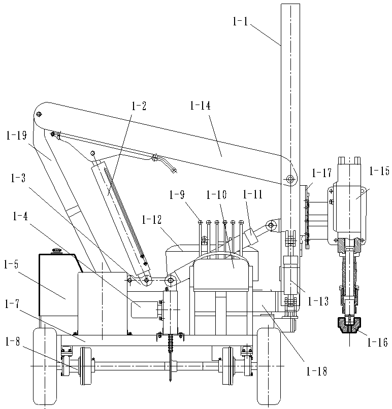
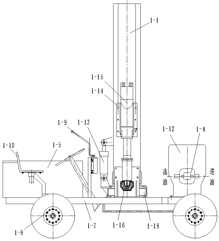
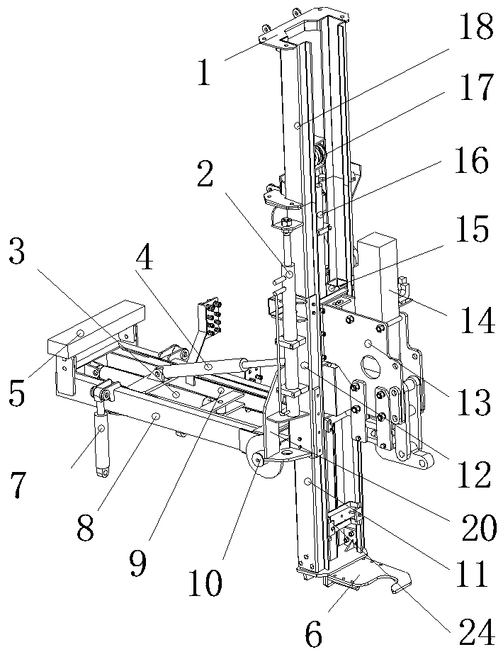
[0057] Example 1: In image 3 , Figure 4 Among them, the working mechanism includes: a column, a limit frame 24, a pile holder 6, a lifting device, a horizontal device, a left and right device, a pitching device and a working device; Device 6; a working device is connected to the column through a lifting device, and the lifting device slides up and down along the column, and drives the working device to move up and down; the column is hinged on one end of the horizontal device through a pitching device, and the column can move laterally with the horizontal device, and The horizontal device can be used as the fulcrum for pitching movement; the bottom of the horizontal device is hinged on the ground, the left and right devices are hinged between the horizontal device or the column and the site, and the horizontal device uses the bottom hinge as the fulcrum, driven by the left and right devices together with the column Make left and right movements.
[0058] exist Figure 8 A...
Embodiment 2
[0080] Example 2: In Figure 4 Among them, it is an embodiment in which a secondary lifting cylinder 4-2 is respectively installed on both sides of the fixed column.
Embodiment 3
[0081] Example 3: In Figure 5 Among them, it is the embodiment that an auxiliary lifting cylinder 4-2 is installed on the rear side of the fixed column.
PUM
Abstract
The invention provides an operating mechanism of a highway guardrail pile driving and pulling machine and belongs to highway guardrail pile driving and pulling machines. The operating mechanism comprises stand columns, a limiting frame, a pile gripper, a lifting device, a transverse device, a left-right device, a pitching device and an operating device. The lifting frame and the pile gripper are connected to the lower portions of the stand columns in sequence. The operating device is connected to the stand columns through the lifting device. The lifting device slides up and down along the stand columns and drives the operating device to move up and down. The stand columns are hinged to one end of the transverse device through the pitching device. The stand columns can do transverse motionalong with the transverse device and can do pitching motion with the transverse device as the fulcrum point. The bottom of the transverse device is hinged to a chassis. The left-right device is hingedbetween the transverse device or the stand columns and the chassis. The transverse device is driven by the left-right device to do left-right motion together with the stand columns with the bottom hinge point with the fulcrum point. The operating mechanism has the advantages that operation is easy; the perpendicularity of driven guardrail piles is high; vibration of the whole machine is small; the service life of the whole machine is prolonged; the operating comfort of working staff is improved.
Description
technical field [0001] The invention relates to a highway guardrail pile driving and pulling machine, in particular to a working mechanism of the highway guardrail pile driving and pulling machine. Background technique [0002] At present, when people are building or maintaining roads, they need to set up anti-collision guardrails on the roads for traffic safety. Generally, anti-collision guardrails are installed on guardrail piles, and guardrail piles need to be driven into the ground with a hydraulic pile driver. The hydraulic pile driver ( figure 1 , figure 2 Middle) includes: column (1-1), lower pressure arm cylinder (1-2), ladder frame (1-3), travel motor (1-4), hydraulic oil tank (1-5), radiator (1- 6), lower frame (1-7), walking assembly (1-8), multi-way operation valve handle (1-9), seat (1-10), pitch cylinder (1-11), diesel engine (1 -12), tilt cylinder (1-13), lower pressure arm (1-14), slide plate (1-17), hydraulic hammer (1-15), piling cap (1-16), transverse ...
Claims
Application Information
Patent Timeline
Application Date:The date an application was filed.
Publication Date:The date a patent or application was officially published.
First Publication Date:The earliest publication date of a patent with the same application number.
Issue Date:Publication date of the patent grant document.
PCT Entry Date:The Entry date of PCT National Phase.
Estimated Expiry Date:The statutory expiry date of a patent right according to the Patent Law, and it is the longest term of protection that the patent right can achieve without the termination of the patent right due to other reasons(Term extension factor has been taken into account ).
Invalid Date:Actual expiry date is based on effective date or publication date of legal transaction data of invalid patent.