
A scanning device for x-ray backscatter imaging system

An imaging system and scanning device technology, applied in the field of scanning devices of X-ray backscatter imaging systems, can solve the problems of difficult processing, large volume, high cost, etc., save installation time and cost, improve stability and reliability, The effect of reducing the difficulty of design and processing

Active Publication Date: 2020-10-09
CHINA INSTITUTE OF ATOMIC ENERGY
View PDF3 Cites 0 Cited by
  • Summary
  • Abstract
  • Description
  • Claims
  • Application Information

AI Technical Summary

Problems solved by technology

The current scanners have the disadvantages of high processing difficulty and high cost. In addition, the existing scanners are large in size and heavy in weight, and the vibration caused by rotation is relatively large, which reduces the reliability of the X-ray backscatter imaging system. The power requirements of the motor are also high
Moreover, the existing scanner needs to occupy a separate installation space, resulting in a large volume of the X-ray backscatter imaging system

Method used


Image

  • A scanning device for x-ray backscatter imaging system
  • A scanning device for x-ray backscatter imaging system
  • A scanning device for x-ray backscatter imaging system

Examples


Embodiment Construction

[0026] The present invention will be further described below in conjunction with the accompanying drawings and embodiments.

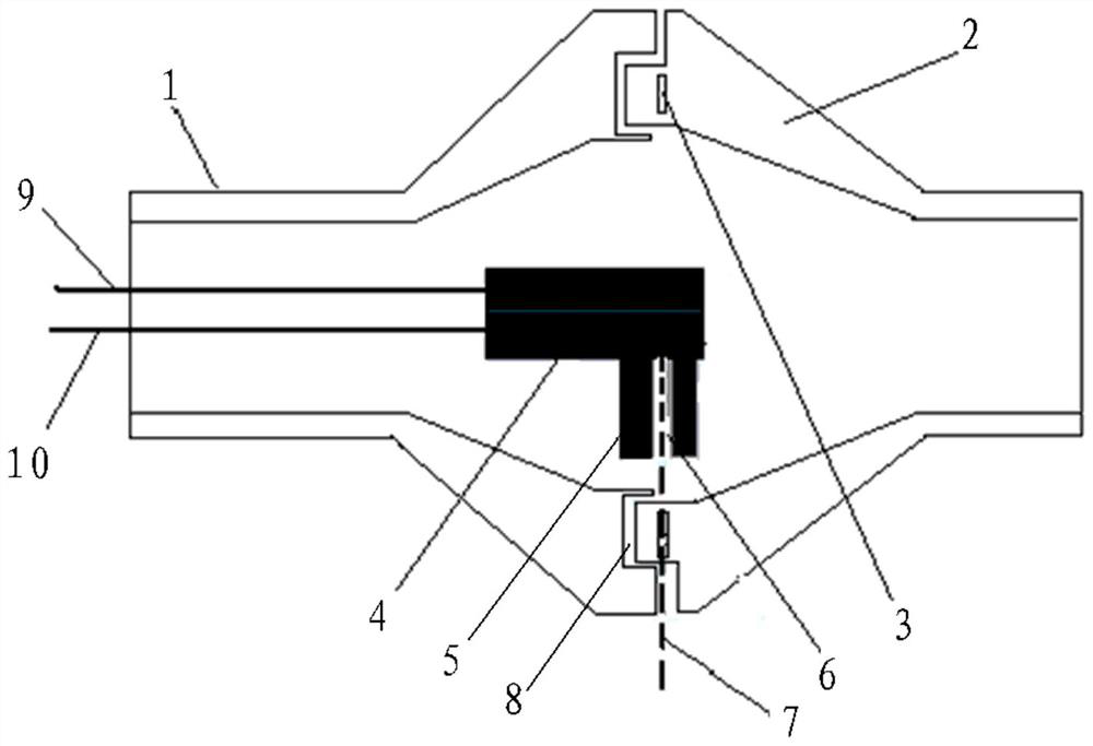
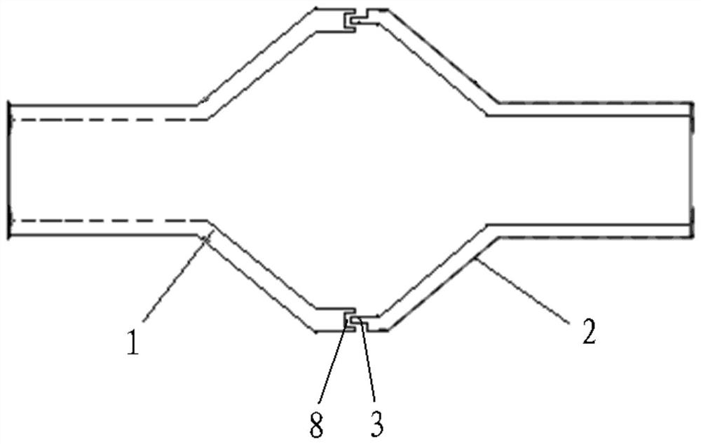
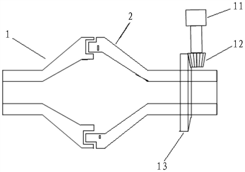
[0027] Such as figure 1 , figure 2 , image 3 As shown, a scanning device for an X-ray backscatter imaging system provided by the present invention includes a fixed housing 1, a rotating housing 2, an exit aperture 3, a track 8, a position sensor 11, a pinion 12, and a transmission wheel 13 Wait.

[0028] The scanning device for the X-ray backscatter imaging system is set on the backscatter imaging equipment stand, wherein the fixed shell 1 and the rotating shell 2 are hollow, and the shell parts of the fixed shell 1 and the rotating shell 2 are cylinders Shaped structure, the inner end of the fixed housing 1 and the rotating housing 2 are opposite to each other (the inner end of the fixed housing 1 is opposite to the inner end of the rotating housing 2), and the fixed housing 1 and the rotating housing 2 are coaxial. The outer end of the fixed cas...


PUM


Abstract

The invention belongs to the field of radiation imaging detection equipment and in particular relates to a scanning device for an X-ray back scattering imaging system. The scanning device is arrangedon a back scattering imaging equipment rack and comprises a fixed shell and a rotary shell, which are coaxial and hollow, and ends of inner sides of the fixed shell and the rotary shell are arranged oppositely; one end of the outer side of the fixed shell is fixedly arranged on the back scattering imaging equipment rack; one end of the outer side of the rotary shell is arranged on the back scattering imaging equipment rack through a bearing; a space capable of containing an X-ray tube provided with a collimator is commonly formed in the ends, which are arranged oppositely, of the inner sides of the fixed shell and the rotary shell; the rotary shell is provided with an emission small hole; a ray beam, which is generated by rotating the X-ray tube around the axis along the rotary shell, canbe emitted through the emission small hole via the collimator to form periodic point scanning. The mutual separation manner of the fixed shell and the rotary shell is convenient for installation and operation; the processing difficulty is reduced, the volume weight of a rotary part is reduced, vibration generated by rotation is reduced and the stability and reliability of equipment are improved.

Description

technical field [0001] The invention belongs to the field of radiation imaging detection equipment, in particular to a scanning device for an X-ray backscatter imaging system. Background technique [0002] As a widely accepted main security inspection technology, the X-ray imaging system can realize rapid inspection of luggage and other items, as well as cargo inspections at various land, sea, and airports (such as cargo inspections at airports, seaports, and land checkpoints, as well as personnel inspections). Carried small packages, luggage inspection). In particular, the security inspection equipment based on X-ray Compton backscatter imaging can effectively provide the geometric shape and spatial distribution characteristics of the object with a lower atomic number and higher density on the surface of the object to be inspected. With transmission scanning, comprehensive inspection information can be obtained. . A system based on X-ray transmission energy detection usua...

Claims


Application Information

Patent Timeline
Patent Type & Authority Patents(China)
IPC IPC(8): G01N23/203
CPCG01N23/203
Inventor 王强张炜郑玉来李永田利军郭凤美杨璐刘超颜静儒田星皓王国宝
Owner CHINA INSTITUTE OF ATOMIC ENERGY
Learn More