Converter and control method thereof
A converter and transformer technology, which is applied in the field of flyback converter and its control, can solve the problems of reducing the conversion efficiency of the converter, large turn-off loss of the output rectifier diode, etc., and achieves the effect of strong structural versatility
- Summary
- Abstract
- Description
- Claims
- Application Information
AI Technical Summary
Problems solved by technology
Method used
Image

Examples
no. 1 example
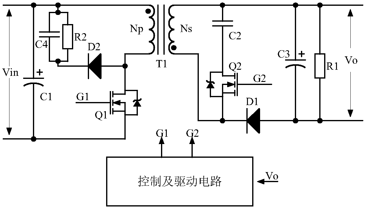
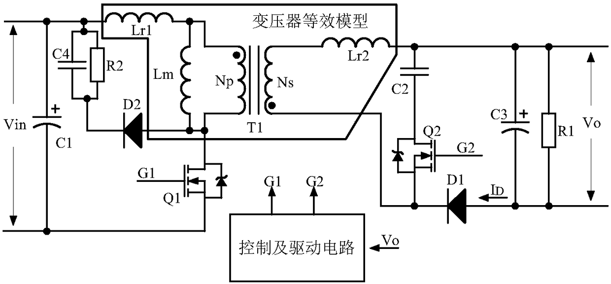
[0045] figure 2 It is a schematic circuit diagram of the first embodiment of the converter for realizing the function of reducing the turn-off loss of the output rectifying diode according to the present invention. The absorption network is connected in parallel with the secondary side of the transformer; the input of the control and drive unit is connected to the output of the converter, one output of the control and drive unit is connected to the primary switch tube of the converter, and the other output of the control and drive unit is connected to the output of the absorption network. The switch tube is connected. Wherein, the absorbing network is composed of a switch tube Q2 and a capacitor C2.
[0046] The connection relationship of the first embodiment of the converter for reducing the turn-off loss of the output rectifying diode in the present invention is as follows:
[0047] The positive pole of the input capacitor C1 is connected to the positive pole of the input...
no. 2 example
[0057] The second example is Figure 9 As shown, the connection relationship is as follows:
[0058] The positive pole of the input capacitor C1 is connected to the positive pole of the input power supply, and connected to one end of the primary side of the transformer T1 and one end of the capacitor C4; the negative pole of the input capacitor C1 is connected to the negative pole of the input power supply, and connected to the source of the switching tube Q1; the transformer The other end of T1 is connected to the drain of the switch tube Q1 and the source of the switch tube Q3; the gate of the switch tube Q1 is connected to the output terminal G1 of the control and drive circuit; the gate of the switch tube Q3 is connected to the output of the control and drive circuit The terminal G3 is connected, the drain of the switch tube Q3 is connected to the other end of the capacitor C4; the anode of the output rectifier diode D1 is connected to the negative pole of the output side,...
no. 3 example
[0062] The third embodiment such as Figure 11 As shown, the flyback topology includes a transformer T1, an input capacitor C1, an output filter capacitor C3, a resistor R1, a diode D1, a diode D2, a diode D3, a main switch Q1 and a switch Q3;
[0063] The positive pole of the input capacitor C1 is connected to the positive pole of the input voltage, and is connected to the drain of the switching tube Q3 and the cathode of the diode D2; the negative pole of the input capacitor C1 is connected to the negative pole of the input voltage, and is connected to the source of the main switching tube Q1, the diode The anode of D3 is connected; the primary terminal of the transformer T1 with the same name is connected with the source of the switch tube Q3 and the cathode of the diode D3; the primary terminal of the transformer T1 with the same name is connected with the drain of the main switch tube Q1 and the anode of the diode D2; The gate of the switch tube Q1 is connected to the fir...
PUM
 Abstract
Description
Claims
Application Information