
Mechanical part cleaning device

A technology for mechanical parts and cleaners, applied in mechanical equipment, springs/shock absorbers, chemical instruments and methods, etc., to achieve the effect of increasing stability and improving shock resistance

Inactive Publication Date: 2018-09-18
丹阳旭铃精密零部件有限公司
View PDF22 Cites 5 Cited by
  • Summary
  • Abstract
  • Description
  • Claims
  • Application Information

AI Technical Summary

Problems solved by technology

The traditional cleaning process generally uses a cleaner to clean the parts, and after cleaning, it is necessary to further check the cleaning effect, further screen out the unqualified parts, and repeat the cleaning. However, for these small batches of parts that need to be cleaned repeatedly, generally A small cleaner that is easy to move is used for repeated cleaning, such as a small ultrasonic cleaner, and the cleaner is generally placed on the bracket. In order to make the movement more convenient, rollers are set at the bottom of the bracket, but the setting of the rollers Added to the instability of the cleaner

Method used


Image

  • Mechanical part cleaning device
  • Mechanical part cleaning device
  • Mechanical part cleaning device

Examples


Embodiment Construction

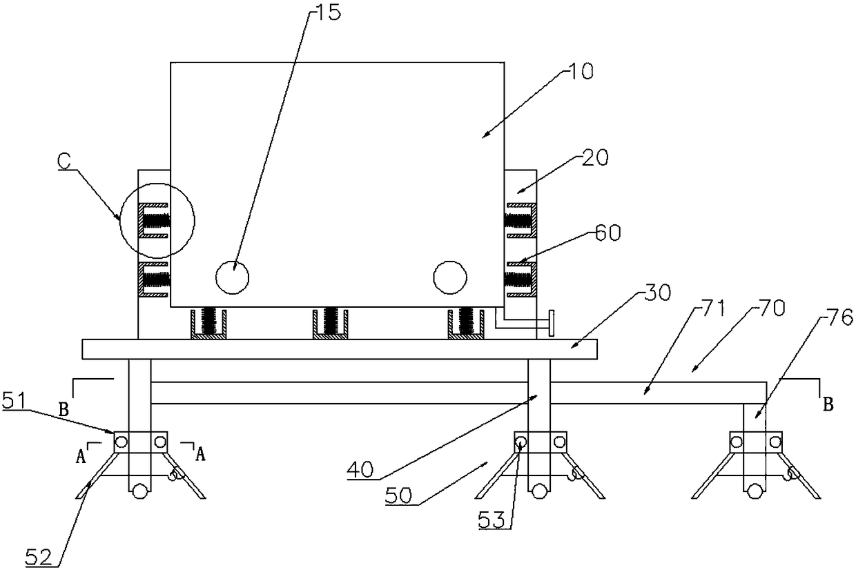
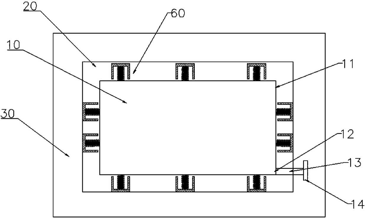
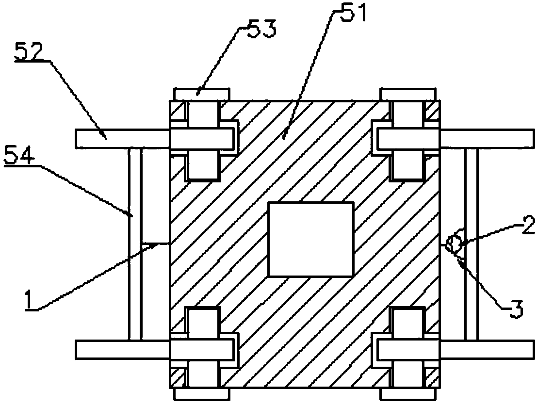
[0023] combine Figure 1 to Figure 8 A kind of mechanical parts washer shown, in this embodiment, includes a washer body 10, an outer shell 20 surrounding the outer side of the washer body 10, a support plate 30 arranged at the bottom of the outer shell 20, and a supporting plate 30. Four support legs 40 distributed in a rectangular shape, an auxiliary bracket 50 arranged on the support legs 40 and a shock absorber 60 arranged between the washer body 10 and the outer shell 20, the bottom of the support legs 40 are provided with a second A pulley, the auxiliary bracket 50 includes a rectangular cover plate 51 sleeved and fixed on the supporting leg 40, auxiliary legs 52 connected to the four corners of the cover plate 51 and bolts 53 connecting the cover plate 51 and the auxiliary leg 52, The top of the auxiliary leg 52 is provided with a through hole, and the cover plate 51 is provided with a groove for accommodating the top of the leg, and both sides of the groove are provide...


PUM


Abstract

The invention provides a mechanical part cleaning device, and belongs to the technical field of part cleaning. The mechanical part cleaning device comprises a cleaning device body, an outer shell body, a supporting plate, supporting landing legs, auxiliary supporting frames and damping devices; the auxiliary supporting frames comprise rectangular sleeve plates which sleeve and are fixed on the supporting landing legs, auxiliary landing legs and bolts, wherein the sleeve plates and the auxiliary landing legs are fixed through the bolts, the auxiliary landing legs can rotate around the bolts, aconnecting rod is arranged between the two auxiliary landing legs located on the same side of each sleeve plate, and at least one pull hook assembly which mutually cooperates is arranged on the two connecting rods corresponding to each sleeve plate; and the damping devices comprise cylindrical partition blocks which are fixed on the inner side of the outer shell body, accommodating grooves with openings facing the cleaning device body are formed in the partition blocks, cylindrical rubber columns are fixed in the centers of the accommodating grooves, springs sleeves the outer sides of the rubber columns, recesses which are in semi-spherical-surface shapes are formed in the tops of the rubber columns, and protrusions which cooperate with the recesses and are in the semi-spherical-surface shapes are arranged on the outer side of the cleaning device body. The mechanical part cleaning device is simple in structure, convenient to move and better in stability.

Description

technical field [0001] The invention belongs to the technical field of parts cleaning, and in particular relates to a mechanical parts cleaner. Background technique [0002] Parts refer to inseparable individual parts in machinery. They are the basic components of the machine and the basic unit in the mechanical manufacturing process. The manufacturing process generally does not require assembly processes, such as pistons, bearing bushes, connecting rod bodies, connecting rod heads, etc. , and the surface roughness is an important technical index reflecting the microscopic geometric shape error of the part surface, and is the main basis for testing the surface quality of the part; whether it is reasonable or not is directly related to the quality, service life and production cost of the product. Workpieces that have just been processed, including newly manufactured equipment, must be properly cleaned before they can meet the requirements for use. The traditional cleaning pr...

Claims


Application Information

Patent Timeline
Patent Type & Authority Applications(China)
IPC IPC(8): B08B3/12B08B13/00F16F15/08
CPCB08B3/12B08B13/00F16F15/085
Inventor 江川君広
Owner 丹阳旭铃精密零部件有限公司
Learn More