Eureka AIR delivers breakthrough ideas for toughest innovation challenges, trusted by R&D personnel around the world.

NOx sensor gas taking pipe for distributed energy tail gas purification DeNOx system

A distributed energy and tail gas purification technology, which is applied in exhaust gas treatment, exhaust devices, machines/engines, etc., can solve the problems of centralized exhaust gas treatment, high cost, difficult exhaust gas purification system, etc., and achieve the goal of improving sampling efficiency Effect

Pending Publication Date: 2018-09-18
NANJING IKAKAT EMISSIONS TECH CO LTD
View PDF0 Cites 0 Cited by
  • Summary
  • Abstract
  • Description
  • Claims
  • Application Information

AI Technical Summary

Problems solved by technology

[0003] 1. The layout of distributed energy is relatively scattered, and it is relatively difficult to treat exhaust gas in a centralized manner; 2. Due to the differences in the environment and fuel used in distributed energy, the concentration of NOx pollutants in exhaust gas produced by different units is not the same, and it is difficult for the engine to leave the factory. 3. Most of the distributed energy engine units use imported engine products, and it is difficult for the exhaust gas purification system to obtain engine working status information; 4. Most of the existing distributed energy units have been put into operation, and the new exhaust gas purification system has been added. The system cannot affect the operation and layout of the original system; 5. Individual distributed energy units use the vehicle SCR system for NOx purification, which is limited by the level of the vehicle SCR system itself, and often requires multiple sets of vehicle SCR systems to meet the requirements. Requirements; 6. The traditional exhaust gas purification system of distributed energy units uses PLC to control the system, which requires specific power supply and distribution and control cabinets, motors and water pumps to complete the system work. The system structure is complex and costly

Method used


Image

  • NOx sensor gas taking pipe for distributed energy tail gas purification DeNOx system
  • NOx sensor gas taking pipe for distributed energy tail gas purification DeNOx system

Examples


Embodiment Construction

[0019] The present invention will be further described in detail below in conjunction with specific embodiments.

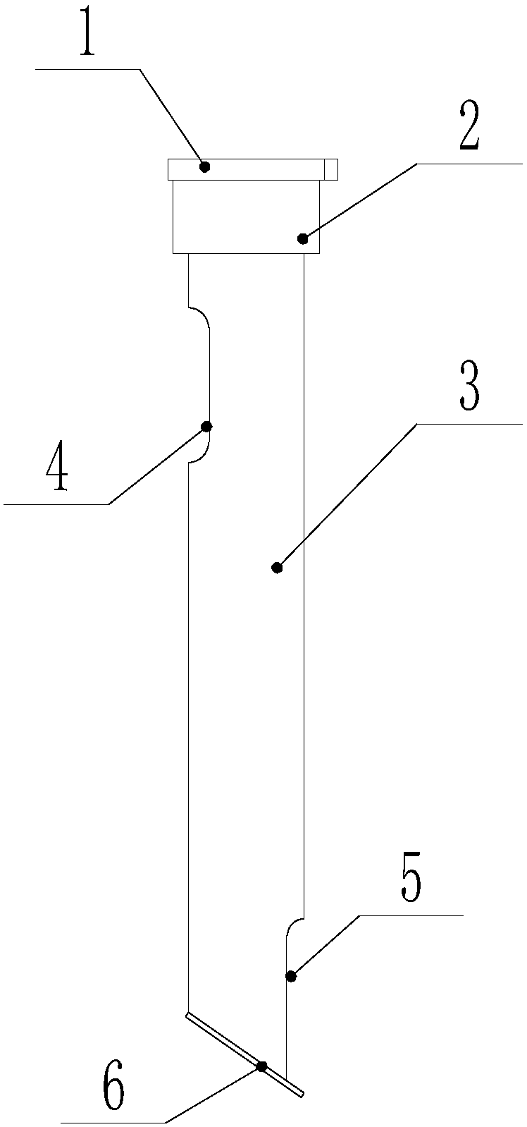
[0020] Such as Figure 1 to Figure 2 The NOx sensor air intake pipe of a distributed energy exhaust purification DeNOx system shown includes a sensor installation top plate 1, a transition pipe 2, an air intake pipe 3 and an oblique sealing plate 6; the transition pipe 2 provides space for sensor installation, and the sensor installation top plate 1 is The sensor provides the installation foundation; the transition pipe 2 and the air intake pipe 3 are connected by welding.

[0021] The oblique sealing plate 6 can effectively increase the intake efficiency and intake volume of exhaust gas.

[0022] The sensor installation top plate 1 is fixed on the top of the transition pipe 2, and the inclined sealing plate 6 is fixed on the lower end of the air intake pipe 3; the lower part of the air intake pipe 3 is provided with an exhaust gas inlet 5, and the upper part of ...


PUM


Abstract

The invention discloses a NOx sensor gas taking pipe for a distributed energy tail gas purification DeNOx system. A sensor mounting top plate is fixed to the top end of a transition pipe; an oblique closing plate is fixed to the lower end of a gas taking pipe; a tail gas inlet is formed in the lower part of the gas taking pipe; a tail gas outlet is formed in the upper part of the gas taking pipe;the tail gas inlet and the tail gas outlet are correspondingly located on the two sides of the gas taking pipe; and the transition pipe is located between the sensor mounting top plate and the gas taking pipe. With the adoption of NOx sensor the gas taking pipe, structures of the tail gas inlet and the tail gas outlet are changed, so that the sampling efficiency of tail gas is improved, and the NOx sensor gas taking pipe ensures that taken gas shows the most authentic concentration information of tail gas NOx. When the gas taking pipe is mounted, the tail gas inlet faces the gas entering direction in which the tail gas is exhausted, so that the gas inlet pressure is increased; the oblique closing plate exists, so that the tail gas entering the gas taking pipe produces certain rising pressure, the tail gas entering the gas taking pipe is pushed out of the tail gas outlet, and the sampling efficiency of the tail gas is further improved. The sensor mounting top plate and the gas taking pipe are arranged eccentrically so as to provide a larger space for sensor mounting.

Description

technical field [0001] The invention relates to the technical field of engine exhaust gas treatment, in particular to an air intake pipe for a NOx sensor of a distributed energy exhaust gas purification DeNOx system. Background technique [0002] With the continuous development of distributed energy technology, more and more distributed energy sources such as landfill gas and natural gas have been utilized, providing a large amount of heat and power resources for the production and life of industrial society. However, with the use of these high-power gas-fired units, the large amount of NOx (nitrogen oxides) pollutants produced during their work has also received more and more attention. According to the emission indicators of atmospheric environmental pollutants formulated by the national and local environmental protection departments, the NOx contained in the tail gas of distributed energy sources also needs to be purified. The traditional distributed energy exhaust gas t...

Claims


Application Information

Patent Timeline
IPC IPC(8): F01N11/00
CPCF01N11/00F01N2560/026Y02T10/40
Inventor 熊飘洋杨曦李科韩丰阳闫政胡广胡飞许玲玲
Owner NANJING IKAKAT EMISSIONS TECH CO LTD
Why Eureka
Eureka Blog
Learn More