
Page turning driving anti-blockage drainage connector

An anti-blocking and page-turning technology, applied in the direction of connecting tubes, suction devices, hypodermic injection devices, etc., can solve the problems of increasing the pollution of the environment and medical personnel, and the design of mechanical removal of obstructions that no one pays attention to. The effect of relieving the obstruction of the lumen

Pending Publication Date: 2018-09-21
SHANGHAI CHANGHAI HOSPITAL
View PDF0 Cites 0 Cited by
  • Summary
  • Abstract
  • Description
  • Claims
  • Application Information

AI Technical Summary

Problems solved by technology

Leakage of drainage fluid or splashing of dirt during the dismantling of the pipeline will increase the possibility of contamination of the environment and medical personnel by blood and body fluids
[0003] At present, the existing drainage joints often only pay attention to the smoothness of the inner wall, the support of the lumen, no discount, and the prevention of slippage. No one has paid attention to the functional design of mechanically removing obstruction.

Method used


Image

  • Page turning driving anti-blockage drainage connector
  • Page turning driving anti-blockage drainage connector
  • Page turning driving anti-blockage drainage connector

Examples


Embodiment Construction

[0025] The present invention will be described in detail below in conjunction with the embodiments and the accompanying drawings. However, the following examples should not be considered as limiting the scope of the present invention.

[0026] In the description of the present invention, it should be noted that the orientation or positional relationship indicated by the terms "upper", "lower", "left", "right", etc. is based on the orientation or positional relationship shown in the drawings, and is only for It is convenient to describe the present invention and simplify the description, but does not indicate or imply that the device or element referred to must have a specific orientation, be constructed and operate in a specific orientation, and thus should not be construed as limiting the present invention.

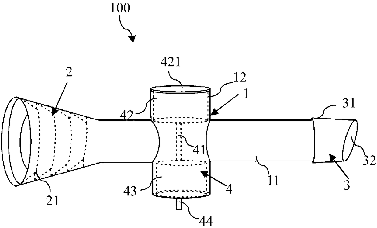
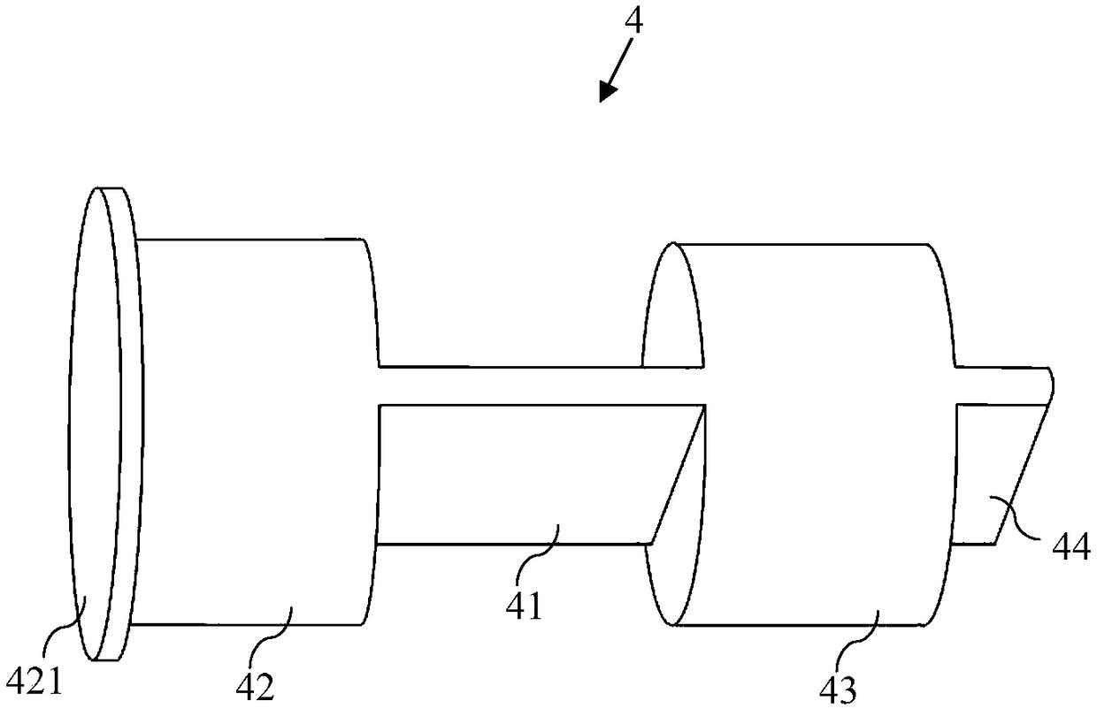
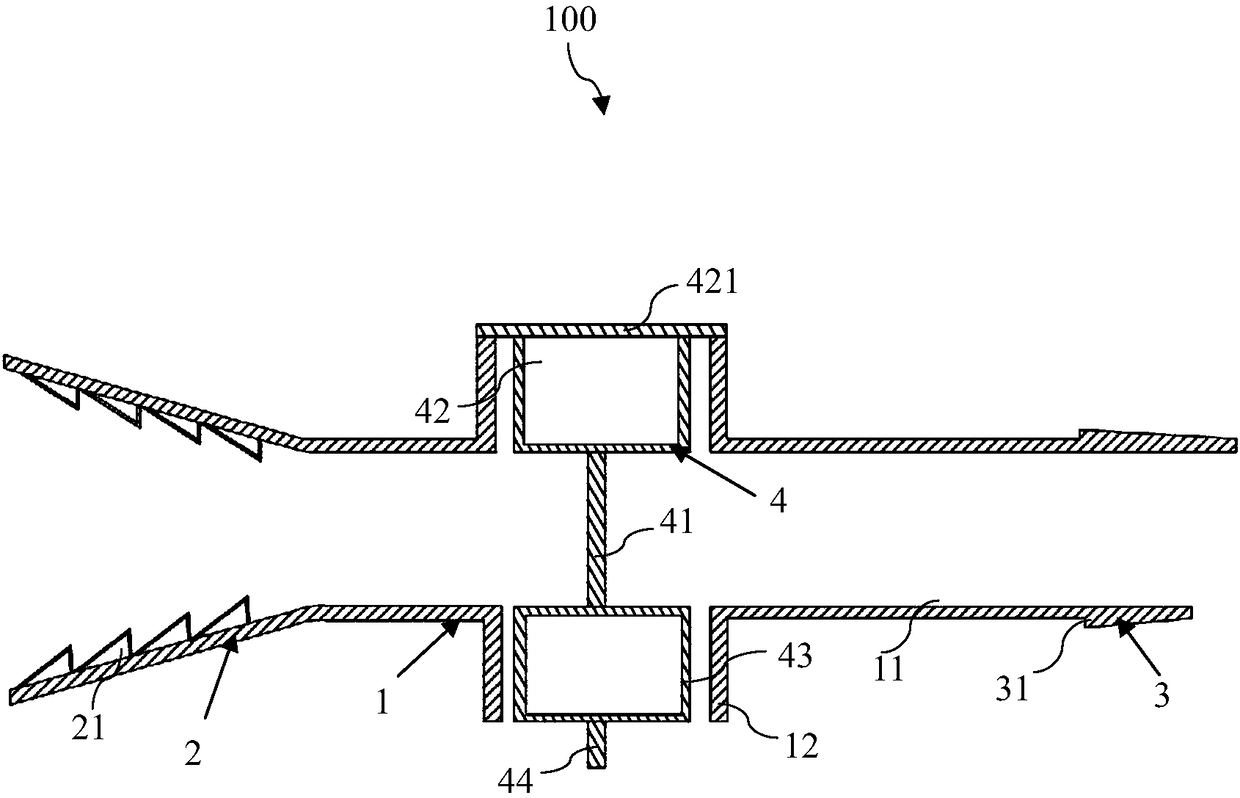
[0027] figure 1 It is a structural schematic diagram of the anti-blocking drainage joint driven by page turning in the embodiment of the present invention; image 3 It...


PUM

PropertyMeasurementUnit
Heightaaaaaaaaaa

Abstract

The invention provides a page turning driving anti-blockage drainage connector which comprises a cross-shaped central pipe, a drainage end connector, a negative pressure end connector and a page turning rotary knob. The drainage end connector and the negative pressure end connector are arranged at the two ends of a long arm of the cross-shaped central pipe respectively, and an inner cavity of thedrainage end connector and an inner cavity of the negative pressure end connector are communicated with the cross-shaped central pipe. The drainage end connector sleeves a drainage pipe on a drainageside and is of a design gradually increasing from the center to the outside, and a continuous step-shaped bayonet is formed on the inner wall of the drainage end connector. The negative pressure end connector is inserted in a drainage pipe on a negative pressure side, one end of the negative pressure end connector is integrally formed at the other end of the long arm of the cross-shaped central pipe, an annular step-shaped bayonet is arranged on the outer wall of the negative pressure end connector and obliquely extends, and the end face of the bayonet is an inclined face. The page turning rotary knob is inserted in an inner cavity of a short arm side of the cross-shaped central pipe, and comprises a flat page turning column arranged in a drainage cavity of the cross-shaped central pipe, two end cap columns and a flat rotary knob arranged on one end cap column and exposed out of the cross-shaped central pipe. The flat page turning column is in a flat shape, and is provided with a wideface and a narrow face, the narrow face is an arc face, and the width of the wide face is the same as the inner diameter of the drainage cavity.

Description

technical field [0001] The invention belongs to the technical field of medical consumables, and in particular relates to a page-turning driven anti-blocking drainage joint. Background technique [0002] In medical clinical practice, especially during operation, the suction device connected with the negative pressure collection device intermittently sucks and removes hemorrhage and accumulated blood during the operation. If the blood in the drainage tube coagulates and dries up, and there is bleeding in the later stage or when flushing and suction are needed, it is often flushed and accumulated at the junction where the diameter of the tube becomes smaller or the inner wall is not smooth, and blood clots occur to block the tube, and the operation is often forced to be interrupted. Wait for the roving nurse to wear gloves to dismantle the connection point of the pipeline, use instruments to remove or clean the clot, and then restore the connection of the pipeline. Leakage of ...

Claims


Application Information

Patent Timeline
IPC IPC(8): A61M1/00A61M39/10
CPCA61M39/10A61M2039/1072A61M1/83A61M1/86
Inventor 胡薇蔡晓冰闫桂玲
Owner SHANGHAI CHANGHAI HOSPITAL
Learn More