Textile bleaching and dyeing exhaust-gas treatment plant

A waste gas treatment device and textile technology, applied in gas treatment, vapor condensation, use of liquid separation agents, etc., can solve the problems of poor pollutant removal effect, low cost, and high treatment cost, achieve better treatment effect, and reduce the content of pollutants. The effect of water volume and simple structure

Pending Publication Date: 2018-09-21
海盐县于城漂染股份有限公司
View PDF0 Cites 9 Cited by
  • Summary
  • Abstract
  • Description
  • Claims
  • Application Information

AI Technical Summary

Problems solved by technology

[0002] In order to prevent the deterioration of the natural environment and protect the green mountains, green water, blue sky, and sea, people pay more and more attention to environmental protection issues. Textile waste gas contains a large amount of harmful smoke, silicone oil, fiber, dye auxiliaries, and industrial acids and alkalis. The composition has brought a certain degree of pollution to the atmospheric environment. China is a large textile country, and there are more than 2,000 bleaching and dyeing enterprises above designated size. In these bleaching and dyeing enterprises, there are several to a dozen setting machines. A large amount of waste gas will be discharged during the production process of finalizing the shape. The waste gas contains a la

Method used


Image

  • Textile bleaching and dyeing exhaust-gas treatment plant

Examples


Embodiment Construction

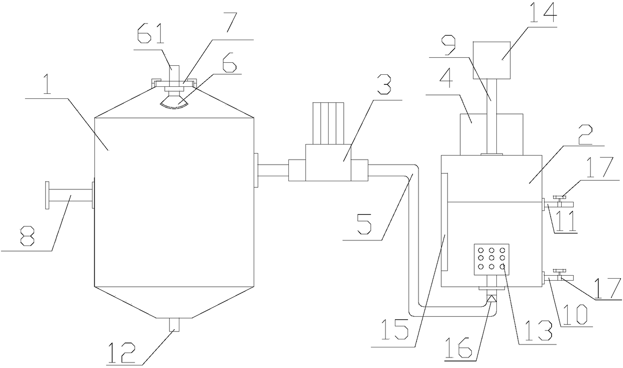
[0017] refer to figure 1 , a textile bleaching and dyeing exhaust gas treatment device according to the present invention, comprising a first tank body 1, a second tank body 2, an air pump 3, a cooler 4, a connecting pipe 5, a spraying device 6, a first tank cover 7, and an air intake pipe 8 , an air outlet pipe 9, a water inlet 10, and a water outlet 11. The upper end of the first tank body 1 is provided with a first tank cover 7, and the first tank cover 7 is detachably connected with the first tank body 1. The lower end of the first tank cover 7 is provided with a spray device 6, the spray device 6, the first tank cover 7 is provided with a spray device inlet pipe 61, and the spray device 6 is connected with the spray device. The device inlet pipe 61 is connected to each other, and the side wall of the second tank body 2 is provided with an air intake pipe 8, and the described air inlet 8 is communicated with the inner cavity of the first tank body 1, and beside the first t...


PUM


Abstract

The invention discloses a textile bleaching and dyeing exhaust-gas treatment plant, which comprises a first tank, a second tank, a suction pump, a cooler, a connecting pipe, a spray device, a first cover, an air inlet pipe, an air outlet pipe, a water inlet and a water outlet. By arranging the two tanks, exhaust gas entering the first tank through an air inlet undergoes first-stage spray purification adsorption through the spray device, and granular pollutants in the exhaust gas are adsorbed by sprayed water; the exhaust gas treated in the first tank is pumped into the second tank through thesuction pump, and the exhaust gas passes through water in the second tank to undergo second-stage adsorption; through an active carbon device arranged at an exhaust port, the exhaust gas can undergo third-stage adsorption, and irritant smell of the exhaust gas can be reduced effectively; and through the cooler arranged on the outer wall of an exhaust pipe, the discharged exhaust gas can be cooled,and water vapor in the exhaust gas is condensed so as to reduce water content of the exhaust gas. In comparison with a traditional technology, the invention has the following advantages: the textilebleaching and dyeing exhaust-gas treatment plant has a simple structure and has better exhaust gas treatment effects, and pollution is reduced.

Description

【Technical field】 [0001] The invention relates to the technical field of environmental protection equipment, especially the technical field of waste gas treatment. 【Background technique】 [0002] In order to prevent the deterioration of the natural environment and protect the green mountains, green water, blue sky, and sea, people pay more and more attention to environmental protection issues. Textile waste gas contains a large amount of harmful smoke, silicone oil, fiber, dye auxiliaries, and industrial acids and alkalis. The composition has brought a certain degree of pollution to the atmospheric environment. China is a large textile country, and there are more than 2,000 bleaching and dyeing enterprises above designated size. In these bleaching and dyeing enterprises, there are several to a dozen setting machines. A large amount of waste gas will be discharged during the production process of finalizing the shape. The waste gas contains a large amount of harmful component...

Claims


Application Information

Patent Timeline
IPC IPC(8): B01D47/02B01D47/06B01D53/00B01D53/02B01D5/00
CPCB01D47/021B01D5/0057B01D47/06B01D53/002B01D53/02B01D2253/102B01D2258/02
Inventor 张永君
Owner 海盐县于城漂染股份有限公司
Why Eureka
Try Eureka