
Dust removal device for textile machine

A technology of dust removal device and textile machinery, which is applied in the direction of combination device, dispersion particle separation, chemical instrument and method, etc., can solve the problems of cotton dust, the influence of the surrounding environment of cotton wool, the effect of dust removal is not obvious, and affect the production efficiency, so as to reduce the risk of Risk of respiratory diseases, significant effect of dust removal, effect of reducing the frequency of dust box cleaning

Inactive Publication Date: 2018-09-21
WUJIANG FUAILIANG TEXTILE
View PDF0 Cites 1 Cited by
  • Summary
  • Abstract
  • Description
  • Claims
  • Application Information

AI Technical Summary

Problems solved by technology

[0002] Textile is to process thread, silk, hemp and other raw materials into silk thread and then weave it into cloth. With the continuous development of science and technology, most of the current textile has been replaced by textile machinery. Dust, etc., when these fluff, cotton dust and other dust enter the equipment, it is easy to cause the failure of the equipment, which affects the production efficiency, and also causes serious environmental pollution. Dust such as lint and cotton dust can cause respiratory diseases, so dust removal devices are often installed in textile workshops
[0003] Most of the existing textile machinery dust removal devices are fixed on the top of the workshop, and the cotton dust and cotton wool are discharged from the workshop through the exhaust fan. Since the workshop is far away from the textile machinery, the dust removal effect is not obvious, and the cotton dust and cotton wool discharged from the workshop will affect the surrounding environment

Method used


Image

  • Dust removal device for textile machine
  • Dust removal device for textile machine
  • Dust removal device for textile machine

Examples


Embodiment Construction

[0022] The following will clearly and completely describe the technical solutions in the embodiments of the present invention with reference to the accompanying drawings in the embodiments of the present invention. Obviously, the described embodiments are only some, not all, embodiments of the present invention. Based on the embodiments of the present invention, all other embodiments obtained by persons of ordinary skill in the art without making creative efforts belong to the protection scope of the present invention.

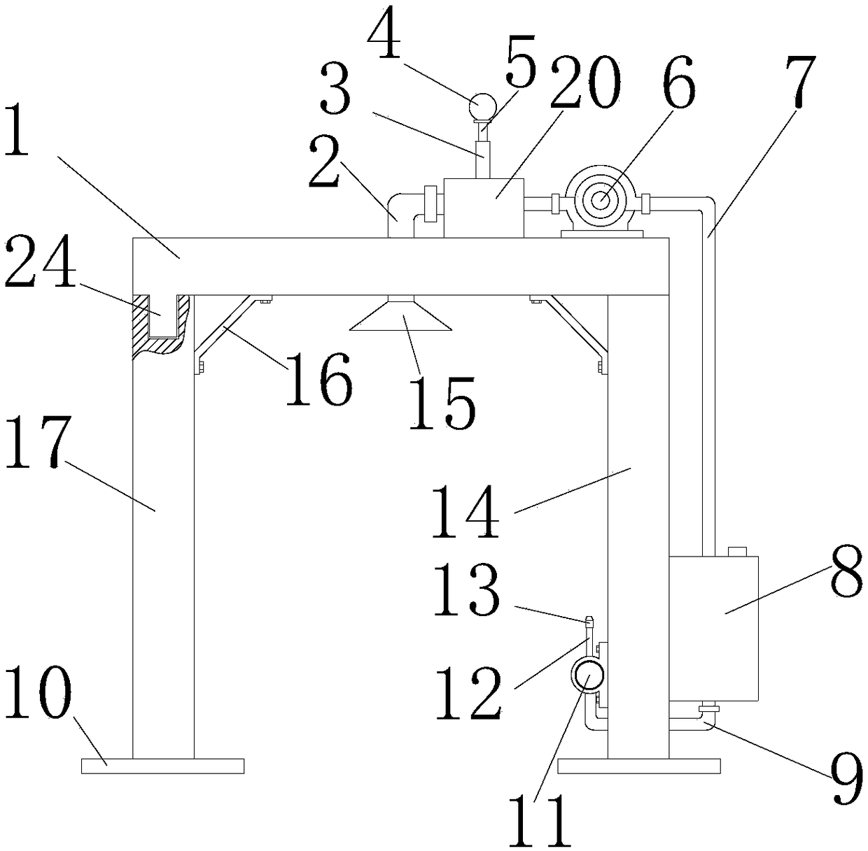
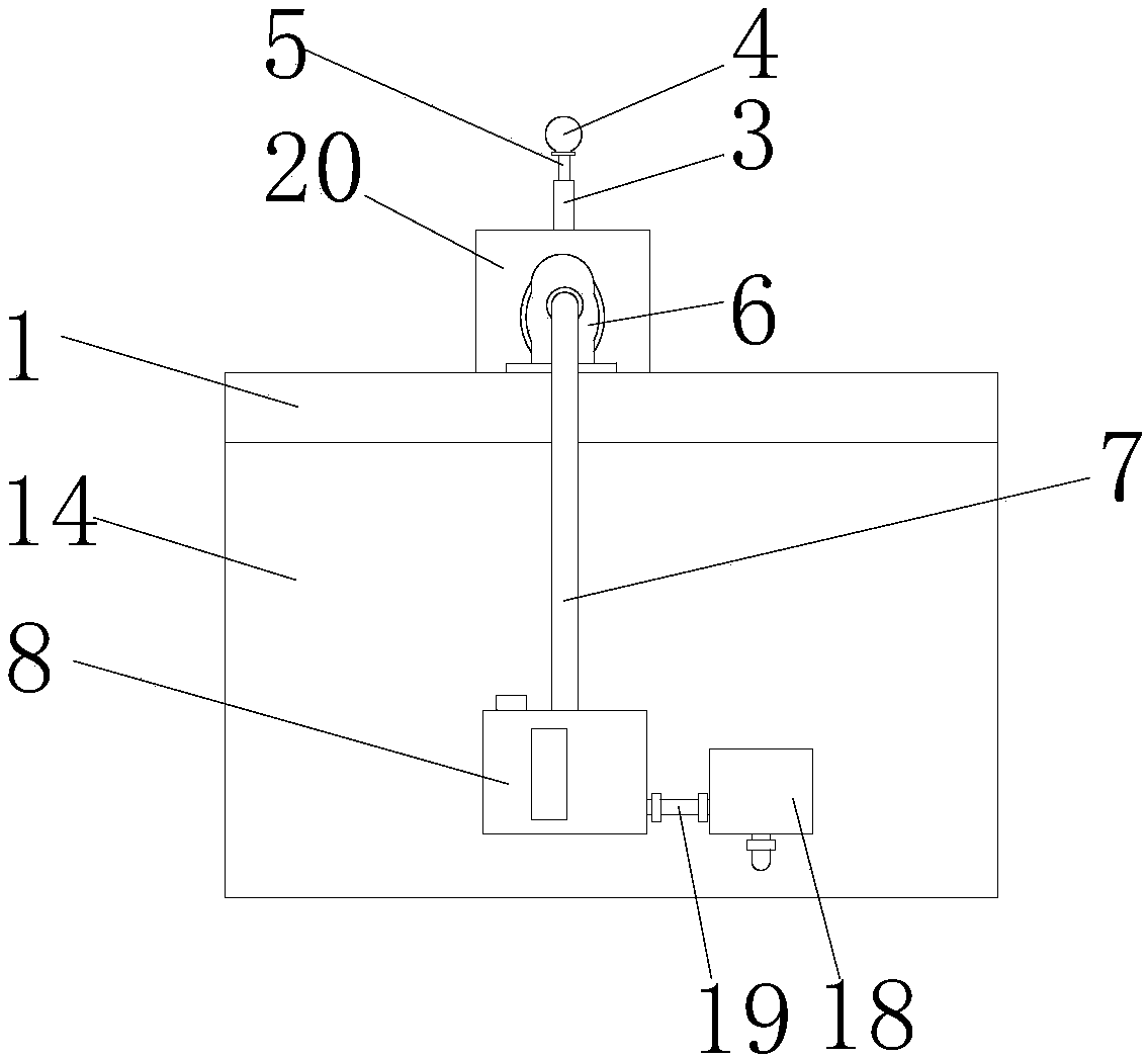
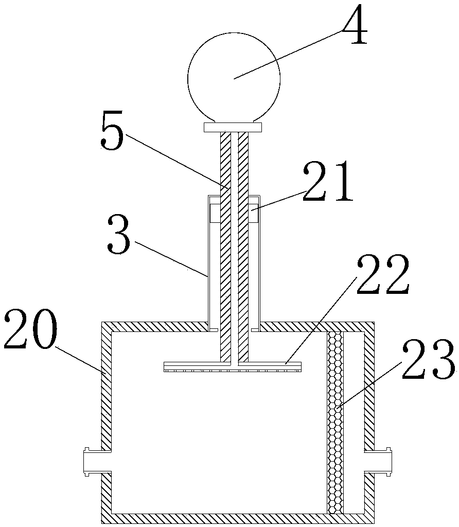
[0023] see Figure 1-3 As shown, a dust removal device for textile machinery includes a top plate 1, a first side plate 14, and a second side plate 17. The tops of the first side plate 14 and the second side plate 17 are provided with grooves, so that the top plate 1 For the installation, the bottom surface of the top plate 1 is provided with bumps 24 at the edges corresponding to each other, and the top plate 1 is snapped together with the grooves of the firs...


PUM


Abstract

The invention discloses a dust removal device for a textile machine. The dust removal device comprises a top plate, a dust collection pipe, a piston barrel, an extrusion ball, a piston rod, a centrifugal fan, an air outlet pipe, a water tank, a first water pipe, mounting feet, a second water pipe, goosenecks, a spray nozzle, a first side plate, a dust hopper, a reinforcement connecting pipe, a second side plate, an atomizer, a third water pipe, a dust collection box, a piston, a press plate, an air filter element and a convex block. According to the dust removal device for the textile machine,the dust collection box is installed on the top of the machine by means of the top plate, the first side plate and the second side plate, and the dust collection box is close to the machine, so thatmost of batt, cotton dust and the like, which are generated by the textile machine, are collected in the dust collection box, the dust removal effect is obvious, the batt, the cotton dust and the like, which enter the machine, can be reduced, and the service life of the machine is prolonged; furthermore, the dust removal device improves the working environment of workers and reduces the risk of respiratory diseases; the dust collection box directly collects the batt, the cotton dust and the like, thus avoiding the impact on the environment.

Description

technical field [0001] The invention relates to a dust removal device, in particular to a dust removal device for textile machinery, which belongs to the technical field of textile machinery application. Background technique [0002] Textile is to process thread, silk, hemp and other raw materials into silk thread and then weave it into cloth. With the continuous development of science and technology, most of the current textile has been replaced by textile machinery. Dust, etc., when these fluff, cotton dust and other dust enter the equipment, it is easy to cause the failure of the equipment, which affects the production efficiency, and also causes serious environmental pollution. Dust such as lint and cotton dust can cause respiratory diseases, so dust removal devices are often installed in textile workshops. [0003] Most of the existing textile machinery dust removal devices are fixed on the top of the workshop, and the cotton dust and cotton wool are discharged from th...

Claims


Application Information

Patent Timeline
IPC IPC(8): B01D50/00
CPCB01D50/60
Inventor 张福明
Owner WUJIANG FUAILIANG TEXTILE
Learn More