Debris flow blocking structure and blocking method

A technology for debris flow and debris flow ditch, applied in dams, gravity dams, etc., can solve the problems of reduced debris flow destructive capacity, reduced debris flow carrying capacity, high engineering volume and cost, and achieves the effect of saving engineering costs, construction time, and resources.

Pending Publication Date: 2018-09-21
范云鹤
View PDF6 Cites 4 Cited by
  • Summary
  • Abstract
  • Description
  • Claims
  • Application Information

AI Technical Summary

Problems solved by technology

[0003] The invention provides a mud-rock flow retaining structure and a retaining method. The retaining structure is restrained by anchor cables. After the mud-rock flow flows through the retaining structure, the large-grained stones are intercepted, the carrying capacity of the mud-rock flow is reduced, and the destructive ability of the mud-rock flow is reduced, thereby effectively preventing

Method used


Image

  • Debris flow blocking structure and blocking method
  • Debris flow blocking structure and blocking method
  • Debris flow blocking structure and blocking method

Examples


Embodiment 1

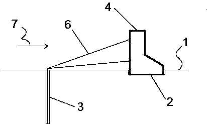
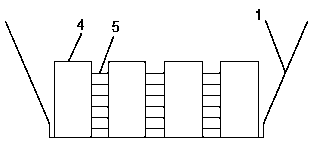
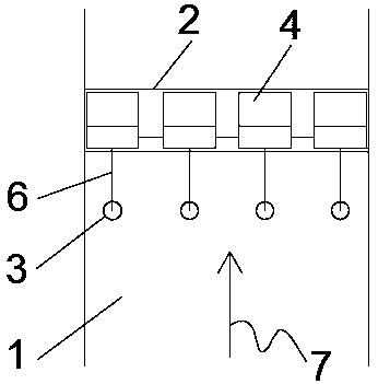
[0029] Such as Figure 1-3 The debris flow blocking structure shown includes an anchor rod 3, a cable 6, a groove 2, a gravity pier 4, and a connecting cable 5. The anchor rod 3 is installed in the debris flow ditch 1, and the diameter of the anchor rod 3 is 80mm-120mm. The anchoring section of the rod 3 extends into the bedrock, and the length of the anchoring section is not less than 400mm. One end of the drag cable 6 is connected to the anchor rod 3, and the other end of the drag cable 6 is connected to the gravity pier 4. The connection between the drag cable 6 and the anchor rod 3, the tension The connection between the cable 6 and the gravity pier 4 can be disassembled. A trench 2 is excavated in the debris flow ditch 1. Several gravity piers 4 are placed in the trench 2. The gravity piers 4 are placed side by side in the trench 2. Between the gravity piers 4 Connected by the cable 5, the diameter of the cable 6 and the cable 5 is not less than 50mm.

[0030] The stay c...


PUM


Abstract

The invention discloses a debris flow blocking structure and a blocking method. The debris flow blocking structure comprises an anchor rod, an inhaul cable, a groove, gravity piers and a connection cable, wherein the anchor rod is arranged in a debris flow ditch, an anchor section of the anchor rod extends into bedrock, one end of the inhaul cable is connected with the anchor rod, the other end ofthe inhaul cable is connected with the gravity piers, the inhaul cable and the anchor rod are detachably connected, the groove is dug in the debris flow ditch, a plurality of gravity piers are arranged in the groove, the gravity piers are arranged in the groove in parallel, and the gravity piers are connected through the connection cable. According to the debris flow blocking structure disclosedby the invention, the anchor rod can provide resistance, and a project amount is reduced; thus, project cost and construction time are saved. The blocking structure can stop large-particle stone in debris flow, so that flushing capacity of the debris flow is weakened, and debris flow disaster is prevented. In addition, the blocking structure disclosed by the invention can be freely disassembled and can be recycled for multiple times.

Description

technical field [0001] The invention belongs to the field of water conservancy engineering, and in particular relates to a debris flow retaining structure and a retaining method. Background technique [0002] Debris flow is an extremely harmful geological disaster. China has a large area of ​​mountains and steep terrain. Concentrated rainfall can easily cause debris flow. The basin of a typical debris flow generally includes the formation area, circulation area, and accumulation area. Debris flow prevention and control projects are generally set in the formation area or circulation area. At present, the most commonly used debris flow control measures are the use of retaining structures, such as steel cable grid dams, grid dams, sieve dams, comb dams, permeable arch dams, etc. The common problem with these dam-type retaining structures is that foundation excavation The engineering volume is large, the dam body engineering volume is also relatively large, the site constructio...

Claims


Application Information

Patent Timeline
IPC IPC(8): E02B7/10
CPCE02B7/10
Inventor 范雲鹤李思滢陈永珍翁杨
Owner 范云鹤
Why Eureka
Try Eureka