
Hall thruster ignition device and method

A Hall thruster and ignition device technology, which is applied in thrust reversers, machines/engines, and the use of plasma, can solve the problems of large payload mass and volume, complex high-voltage power supply technology, etc., to improve ignition reliability, The effect of reducing the mass and volume of the payload and simplifying the complexity of the technical design

Active Publication Date: 2018-09-21
HARBIN INST OF TECH
View PDF5 Cites 6 Cited by
  • Summary
  • Abstract
  • Description
  • Claims
  • Application Information

AI Technical Summary

Problems solved by technology

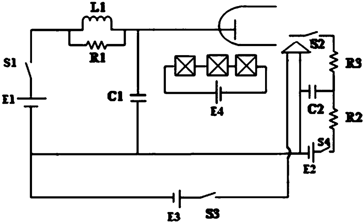
[0003] In the existing ignition mode, when the discharge power switch S1 is closed, the capacitor C1 in the filter module is charged, but an electric field cannot be directly formed between the cathode contact electrode and the cathode negative electrode to extract electrons, and an additional high-voltage ignition is required. The power supply and a controllable ignition switch add high voltage to the contact pole of the cathode to realize the ignition and start of the Hall thruster, but there are limitations in the high-voltage power supply technology, the payload quality and the volume of the power supply occupying space.

Method used


Image

  • Hall thruster ignition device and method
  • Hall thruster ignition device and method
  • Hall thruster ignition device and method

Examples


Embodiment 1

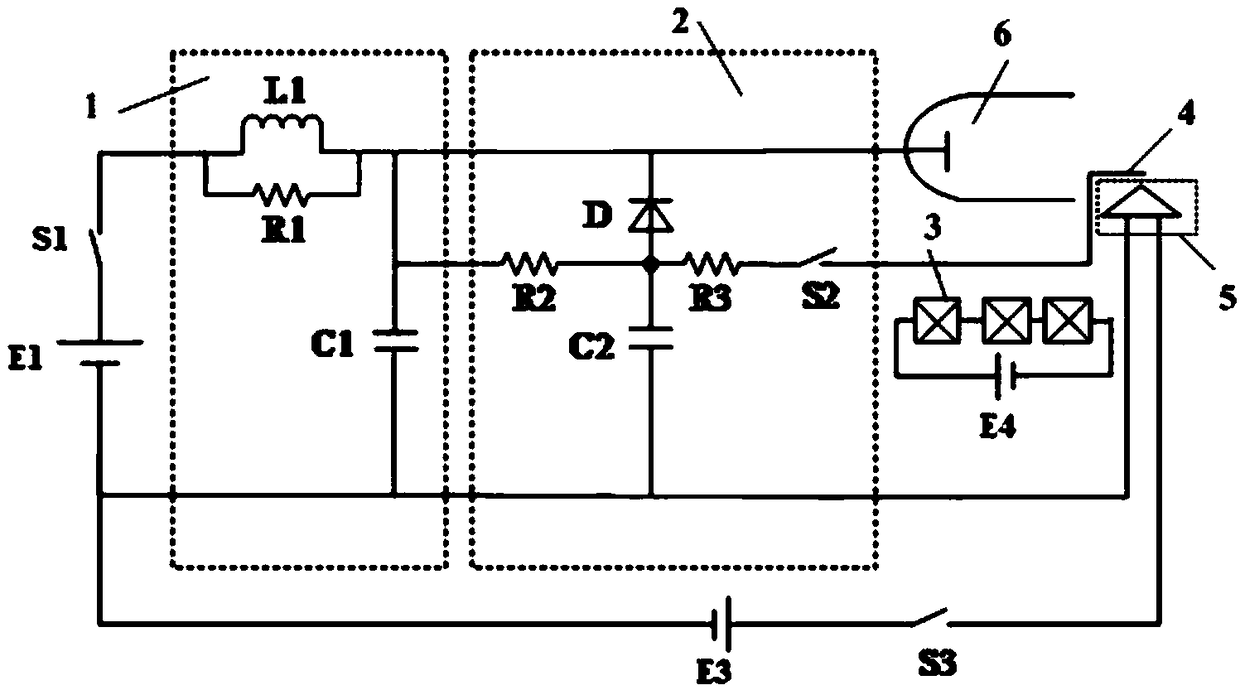
[0035] figure 2 It is a structural schematic diagram of the ignition device of the Hall thruster according to the embodiment of the present invention.

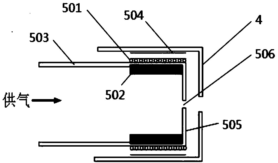
[0036] image 3 It is a schematic diagram of the cathode structure of the Hall thruster in the embodiment of the present invention.

[0037] Such as figure 2 with image 3 As shown, the Hall thruster ignition device provided by the present invention includes: a discharge unit, a filter unit 1, an ignition circuit unit 2, a Hall thruster and a heating unit. The discharge unit includes a discharge power source E1 and a discharge power switch S1, and the discharge power source E1 is connected to the discharge power switch S1. The filter unit 1 includes an inductor L1, a resistor R1 and a capacitor C1. One of the two ends formed by the parallel connection of the inductor L1 and the resistor R1 is connected to the high voltage side of the discharge unit, the other end is connected to one end of the capacitor C1, and the other...

Embodiment 2

[0051] The difference between this embodiment and the first embodiment is that the current-limiting resistor R3=10Ω, the diode D adopts a plurality of diodes connected in series and the reverse cut-off voltage is greater than the ignition voltage, and other components and connections are the same as the first embodiment.

Embodiment 3

[0053] The difference between this embodiment and the first embodiment is that the current-limiting resistor R3=5Ω, the diode D adopts a plurality of diodes connected in series and the reverse cut-off voltage is greater than the ignition voltage, and other components and connections are the same as those of the first embodiment.

[0054] A smaller current-limiting resistor R3 can make more electric energy on the charging capacitor C2 be applied to the cathode contact 4 , thereby extracting electrons faster, improving ignition reliability and shortening ignition time. However, the current-limiting resistor R3 cannot be infinitely small, otherwise the electric energy on the charging capacitor C2 will be applied to the cathode contact electrode 4 instantly, which will have a great impact on the cathode contact electrode 4 and cause the cathode 5 of the Hall thruster to be damaged.


PUM


Abstract

The invention discloses a Hall thruster ignition device and method. The high-voltage side of a discharge unit in the device is connected with a first input end of a filtering unit, and the low-voltageside of the discharge unit is connected with a second input end of the filtering unit. A first output end of the filtering unit is connected with one end of a charge resistor, a cathode of a diode and an anode of a Hall thruster, and a second output end of the filtering unit is connected with one end of a charge capacitor and a cathode of the Hall thruster. The other end of the charge resistor, the other end of the charge capacitor, one end of a current-limiting resistor and an anode of the diode are connected together. The other end of a current-limiting resistor R3 is connected with one endof an ignition switch in series, and the other end of the ignition switch is connected with a cathode touch pole of the Hall thruster. The low-voltage side of a heating unit is connected with the low-voltage side of the discharge unit, and the high-voltage side of the heating unit is connected with a cathode of the Hall thruster. The design complexity of the ignition power source technology can be simplified, the effective load mass and volume of a power source space occupation device are reduced, and the ignition reliability is improved.

Description

technical field [0001] The invention relates to the technical field of Hall effect electric thrusters, in particular to an ignition device and method for a Hall effect electric thruster. Background technique [0002] Due to its simple structure, appropriate specific impulse and high efficiency, Hall thrusters are widely used in space propulsion tasks such as satellite position maintenance and orbit change. The ignition and start-up process is the first step in the orbital operation of the thruster, and it is also the most critical step. figure 1 It is a structural schematic diagram of the Hall thruster ignition device in the background technology, such as figure 1 As shown, the traditional Hall thruster generally completes the ignition and realizes continuous and stable discharge through the following processes: First, the cathode supplies a certain amount of xenon gas, and the heating power switch S3 is closed to supply current to the cathode heater to heat the cathode emi...

Claims


Application Information

Patent Timeline
Patent Type & Authority Applications(China)
IPC IPC(8): F03H1/00
CPCF03H1/0075F03H1/0093
Inventor 魏立秋丁永杰于达仁成渭民
Owner HARBIN INST OF TECH
Learn More