A unified terminal for radiation and convection coupled heat transfer

A technology of radiation heat exchange and coupled heat exchange, which is applied in heating methods, household heating, household heating, etc., can solve the problem of serialization and standardization of unfavorable convection and radiation coupling heat exchange terminals, and the increase of space occupied by air flow resistance equipment , Affect the application and promotion of the combination of flow and radiation, etc., to achieve the effect of improving the comprehensive heat exchange efficiency, compact size, and small footprint

Active Publication Date: 2020-09-01
HEFEI GENERAL MACHINERY RES INST +1
View PDF9 Cites 0 Cited by
  • Summary
  • Abstract
  • Description
  • Claims
  • Application Information

AI Technical Summary

Problems solved by technology

Take the Chinese patent publication, whose publication number is CN 102538142 A, and the patent titled "radiation and air-conditioning cooling and heating integrated system" as a representative. This patent combines radiant panels and fan coils for cooling (warming), However, the fan coil unit has high construction cost, complex operation mode, complex maintenance and high cost, which will easily cause the overall structure to be huge and occupy too much space. Since the terminal form of a unified whole is not formed, this is not conducive to the future development of convection and radiation coupled heat exchange terminals. Product serialization and standardization development, which in turn affects the promotion of combined applications of convection and radiation
[0005] The invention patent with the publication number CN 105180266 A "a cylindrical radiation convection heat exchanger and its heat exchange treatment method" is another representative, which combines natural convection and radiation heat exchange methods to form an integral heat exchanger The air flows inside the cylindrical heat exchanger, but the heat transfer coefficient of natural convection is low, and the advantages of the convection method cannot be fully utilized, and it is difficult to make up for the shortcomings of the radiation end. If it is necessary to increase the heat supply (cold) of the heat exchanger The volume of the heat exchanger increases greatly, resulting in a large increase in air flow resistance and equipment footprint

Method used


Image

  • A unified terminal for radiation and convection coupled heat transfer
  • A unified terminal for radiation and convection coupled heat transfer
  • A unified terminal for radiation and convection coupled heat transfer

Examples


Embodiment 1

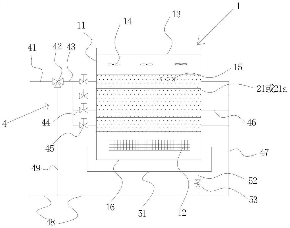
[0052] Such as figure 1 , 2a , 2b, and 3, a radiation and convection coupled heat transfer unified end, roughly rectangular in shape, including the end body 1, radiation heat exchange component 2, convective heat exchange component 3, water supply and return component 4, condensed water drainage Component 5; the radiation heat exchange component 2 is installed on the outer surface of the terminal body 1, including a plurality of radiation heat exchange plates 21 arranged side by side from top to bottom, and the plurality of radiation heat exchange plates 21 are welded and connected to each other. There is a cavity for the flow of the heat exchange medium, and the cavity inside the radiation heat exchange component 2 is connected to the water inlet of the water supply and return component 4; the convective heat exchange component 3 is installed inside the terminal body 1, including a convective heat exchange tube 31 , one end of the convection heat exchange tube 31 communicate...

Embodiment 2

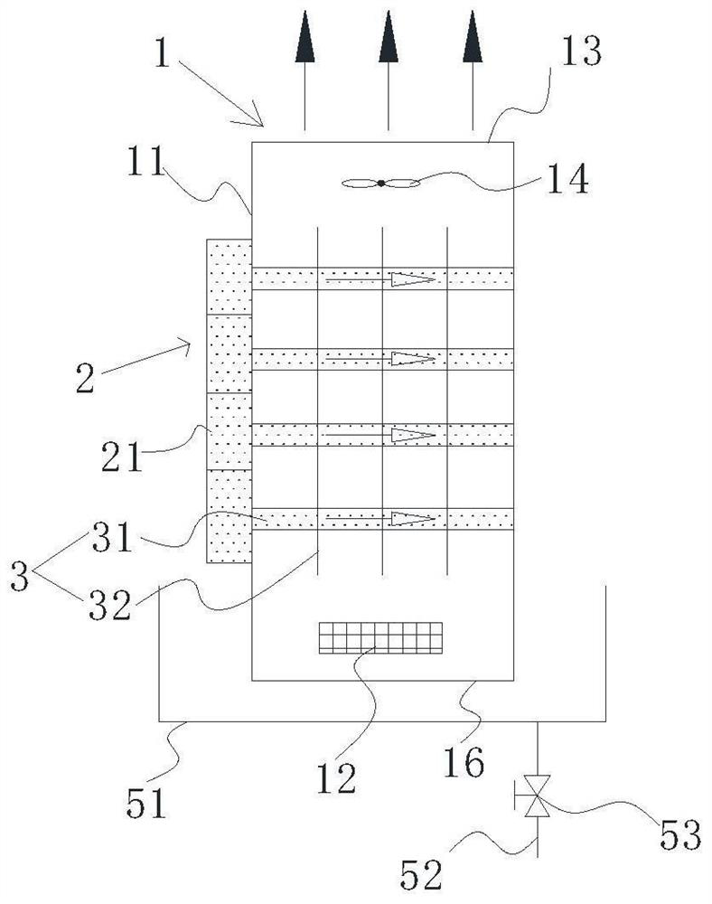
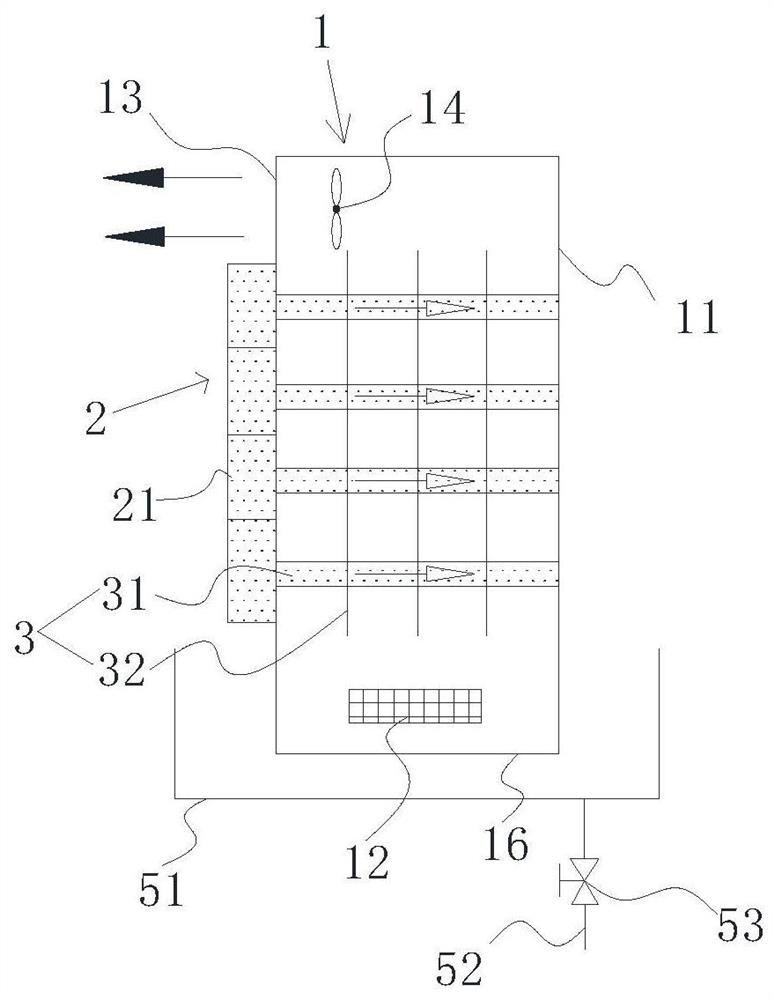
[0056] Such as Figure 4 , 5a , 5b, and 6, a radiation and convection coupling heat exchange unified terminal, which is roughly in the shape of a cuboid, including the terminal body 1, radiation heat exchange components 2, convective heat exchange components 3, water supply and return components 4, and condensed water drainage Component 5; the radiation heat exchange component 2 is installed on the outer surface of the terminal body 1, including a plurality of radiation heat exchange plates 21 arranged side by side from top to bottom, and the plurality of radiation heat exchange plates 21 are welded and connected to each other. There is a cavity for the flow of the heat exchange medium, and the cavity inside the radiation heat exchange component 2 is connected to the water outlet of the water supply and return component 4; the convective heat exchange component 3 is installed inside the terminal body 1, including a convective heat exchange tube 31 , one end of the convection ...

Embodiment 3

[0060] Such as figure 1 , 7a, 7b, and 8, a radiation and convection coupled heat exchange unified terminal, which is roughly in the shape of a cuboid, including the terminal body 1, the radiation heat exchange component 2, the convective heat exchange component 3, the water supply and return component 4, and the condensed water drainage Component 5; the radiation heat exchange component 2 includes a first radiation heat exchange component 21a and a second radiation heat exchange component 21b respectively arranged on both sides of the terminal body, and the first radiation heat exchange component 21a and the second radiation heat exchange component 21b both include The radiation heat exchange plate, a plurality of radiation heat exchange plates arranged side by side from top to bottom are welded and connected to each other, and a cavity for the flow of heat exchange medium is provided inside the radiation heat exchange plate; the convective heat exchange component 3 is install...


PUM


Abstract

The invention belongs to the field of air conditioner heat exchanging tail ends, and particularly relates to a radiation and convection coupled heat exchanging unified tail end. The radiation and convection coupled heat exchanging unified tail end comprises a tail end body, a radiation heat exchanging assembly, a convection heat exchanging assembly and a return water supplying assembly. The radiation heat exchanging assembly is installed on the outer side face of the tail end body and comprises a radiation heat exchanging plate. The radiation heat exchanging plate is internally provided with acavity for a heat exchanging medium to flow. The cavity in the radiation heat exchanging assembly communicates with the return water supplying assembly. The convection heat exchanging assembly is installed in the tail end body and comprises a convection heat exchanging pipe and fins. The two ends of the convection heat exchanging pipe communicate with the cavity and the return water supplying assembly correspondingly. The tail end body is internally provided with a draught fan. The radiation and convection coupled heat exchanging unified tail end has the beneficial effects that the unified tail end is simple in structure and integrally compact, less space is occupied, relatively high heat exchanging efficiency is achieved, advantages of convection heat exchanging and radiation heat exchanging are sufficiently complemented to each other, and different indoor comfort requirements can be flexibly met.

Description

technical field [0001] The invention belongs to the field of air-conditioning heat exchange terminals, and in particular relates to a radiation and convection coupled heat exchange unified terminal. Background technique [0002] At present, the working mode of the air conditioner terminal is mainly divided into convection mode and radiation mode. Among them, the convection mode is mainly represented by fan coil unit and indoor air conditioner air supply; the common practice of radiation mode is to attach the heat exchange tube (coil) to the Metal plates or other materials are represented by the formation of radiant floors, roofs, walls, etc. The heat exchange efficiency of this type of radiation is low. There are many heat transfer links. On the other hand, the heat exchange tube and the radiant plate are in a tangential relationship, and the two are in line contact, so the heat transfer area is small. In addition, the construction and maintenance between the radiant plate a...

Claims


Application Information

Patent Timeline
Patent Type & Authority Patents(China)
IPC IPC(8): F24F13/22F24F13/30
CPCF24F13/22F24F13/30
Inventor 袁旭东樊海彬贾磊宋有强周俊海曲继坤王智文许敬德夏玲胡爱民罗小鹏
Owner HEFEI GENERAL MACHINERY RES INST
Why Eureka
Try Eureka