
New energy automobile motor with efficient heat dissipation

A new energy vehicle, high-efficiency technology, applied in the direction of electromechanical devices, electrical components, mechanical equipment, etc., can solve the problems of low heat dissipation efficiency, motor damage, time-consuming and labor-intensive, etc., and achieve the effect of good effect, convenient operation and simple structure.

Pending Publication Date: 2018-09-21
WUHU SUNYANG INFORMATION CONSULTATION
View PDF8 Cites 1 Cited by
  • Summary
  • Abstract
  • Description
  • Claims
  • Application Information

AI Technical Summary

Problems solved by technology

[0002] Today, with the rapid development of the automobile industry, new energy vehicles have begun to be accepted by consumers due to their advantages of environmental protection and energy saving. The biggest difference between new energy vehicles and traditional vehicles lies in their engines. There are a large number of high-precision instruments, and its motor has low heat dissipation efficiency, and the surrounding instruments are easily affected by high temperature; there are certain disadvantages in the use of existing automotive motors. First of all, the existing new energy automotive motors generally use air cooling Carry out heat dissipation, the heat dissipation efficiency is low, and the car motor is easy to overheat, causing damage to the motor. Secondly, the traditional car motors are connected by separate bolts. The bolts are distributed in every corner of the motor, which is very inconvenient when the motor needs to be disassembled and repaired. , time-consuming and labor-intensive, which has brought a certain impact on users. Therefore, we propose a new energy vehicle motor with efficient heat dissipation

Method used


Image

  • New energy automobile motor with efficient heat dissipation
  • New energy automobile motor with efficient heat dissipation
  • New energy automobile motor with efficient heat dissipation

Examples


Embodiment Construction

[0018] In order to make the technical means, creative features, goals and effects achieved by the present invention easy to understand, the present invention will be further described below in conjunction with specific embodiments.

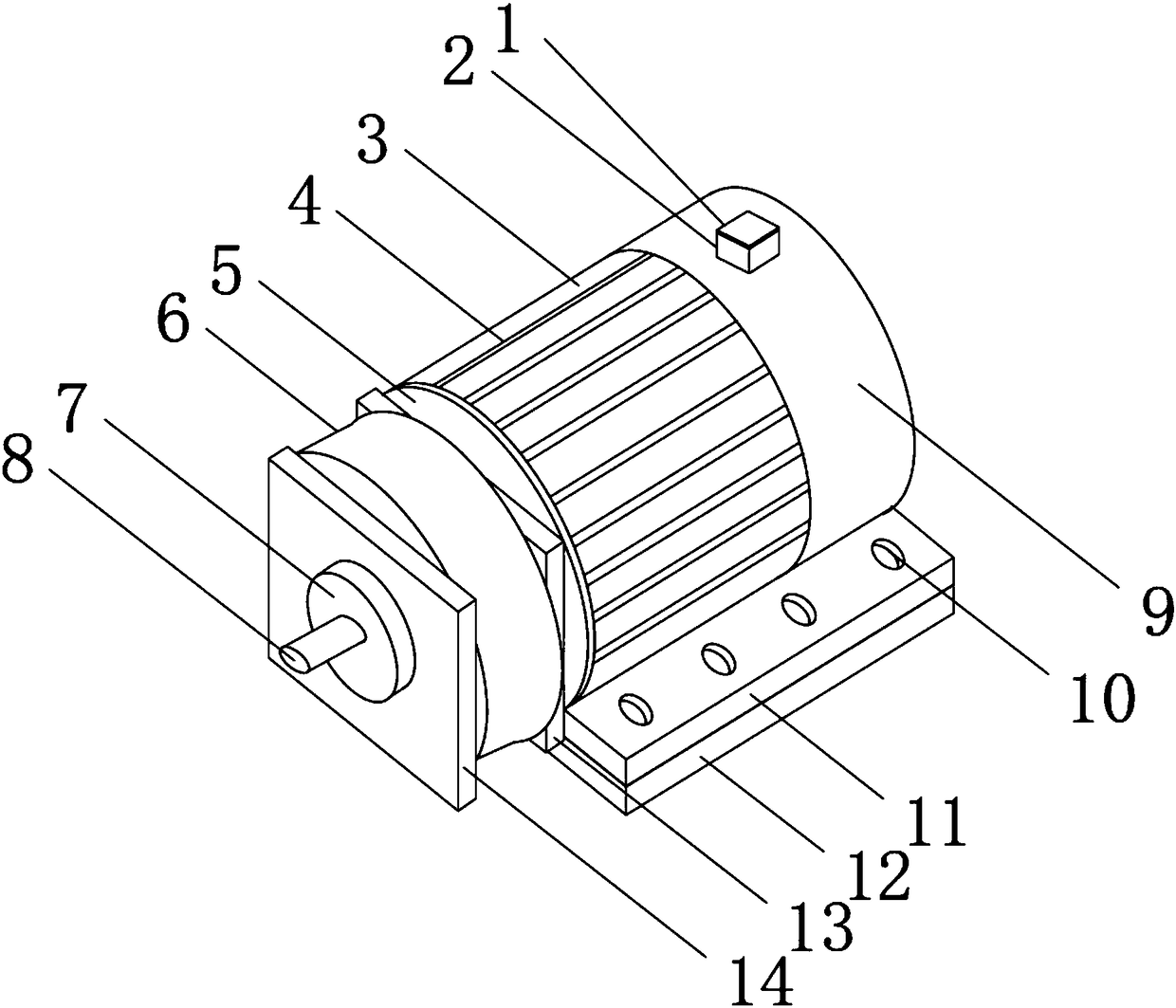
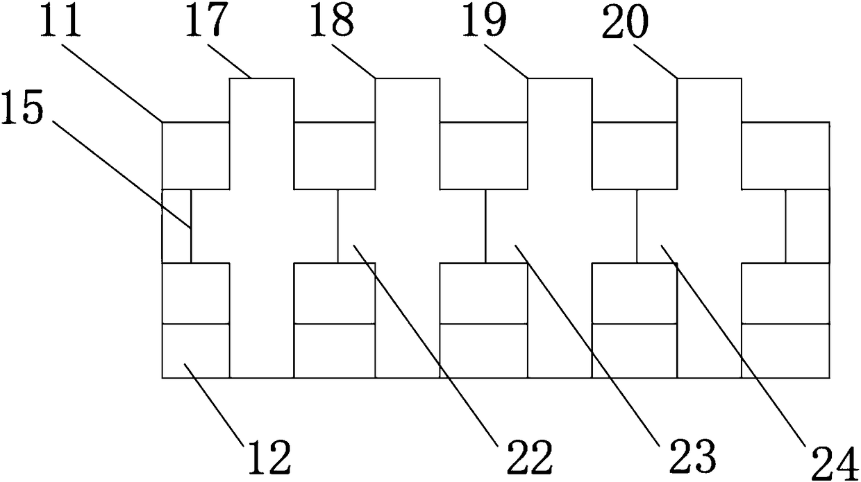
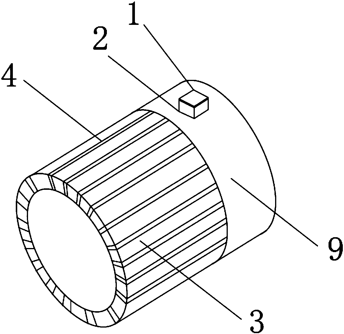
[0019] Such as Figure 1-4 As shown, a high-efficiency heat dissipation new energy automobile motor includes a motor body 5, a first limiting plate 13 is movably installed on the outer surface of the front end of the motor body 5, the first limiting plate 13 is used to fix the rotating disk 6, and the second A rotating disk 6 is movably installed on the outer surface of the front end of a limiting plate 13, and a second limiting plate 14 is movably installed on the outer surface of the front end of the rotating disk 6, and the outer surface of the front end of the second limiting plate 14 is movably connected with the coaxial rotating disk 7 The outer surface of the front end of the coaxial turntable 7 is movably connected with a rotating connecti...


PUM


Abstract

The invention discloses a new energy automobile motor with efficient heat dissipation, which comprises a motor main body, wherein a first limit plate is movably arranged at the outer surface of the front end of the motor main body; a rotating disc is movably arranged at the outer surface of the front end of the first limiting plate; a second limit plate is movably arranged at the outer surface ofthe front end of the rotating disc; the outer surface of the front end of the second limit plate is movably connected with a coaxial rotating disc; the outer surface of the front end of the coaxial rotating disc is movably connected with a rotating connecting shaft; the outer surface of the motor main body is coated with a water cooling layer; the external surface of one side of the water coolinglayer is movably connected with a connecting plate, and the outer surface of the upper end of the connecting plate is provided with a threaded hole. According to the invention, the automobile motor with efficient heat dissipation is provided with the water cooling layer and a first gear, can rapidly dissipate heat to the automobile motor, and can facilitate the disassembly and installation of theautomobile motor, thereby bringing better use prospect.

Description

technical field [0001] The invention relates to the field of automobile motors, in particular to a new energy automobile motor with high heat dissipation. Background technique [0002] Today, with the rapid development of the automobile industry, new energy vehicles have begun to be accepted by consumers due to their advantages of environmental protection and energy saving. The biggest difference between new energy vehicles and traditional vehicles lies in their engines. There are a large number of high-precision instruments, and its motor has low heat dissipation efficiency, and the surrounding instruments are easily affected by high temperature; there are certain disadvantages in the use of existing automotive motors. First of all, the existing new energy automotive motors generally use air cooling Carry out heat dissipation, the heat dissipation efficiency is low, and the car motor is easy to overheat, causing damage to the motor. Secondly, the traditional car motors are ...

Claims


Application Information

Patent Timeline
IPC IPC(8): H02K9/19H02K5/20H02K5/10H02K5/00F16H57/023
CPCH02K5/00H02K5/10H02K5/20H02K9/19F16H57/023
Inventor 赵文娟赵文波
Owner WUHU SUNYANG INFORMATION CONSULTATION
Learn More