CMOS driver applied to output signal slew rate control

An output signal, slew rate technology, applied in the direction of automatic power control, electrical components, etc., can solve the problems of large changes in driving capability, changes in output signal slew rate, etc., to achieve the effect of improving process deviation

Active Publication Date: 2018-09-21
XI AN JIAOTONG UNIV
View PDF3 Cites 0 Cited by
  • Summary
  • Abstract
  • Description
  • Claims
  • Application Information

AI Technical Summary

Problems solved by technology

[0004] The object of the present invention is to provide a CMOS driver applied to output signal slew rate control, to solve the problem that the traditional output signal slew rate control driver has a relatively large change in driving capability under the influence of process deviation, working environment temperature change and power supply voltage change. The problem of large changes in the output signal slew rate

Method used


Image

  • CMOS driver applied to output signal slew rate control
  • CMOS driver applied to output signal slew rate control
  • CMOS driver applied to output signal slew rate control

Examples


Embodiment Construction

[0021] In order to better illustrate the purpose and advantages of the present invention, the present invention will be further described below in conjunction with the accompanying drawings and embodiments.

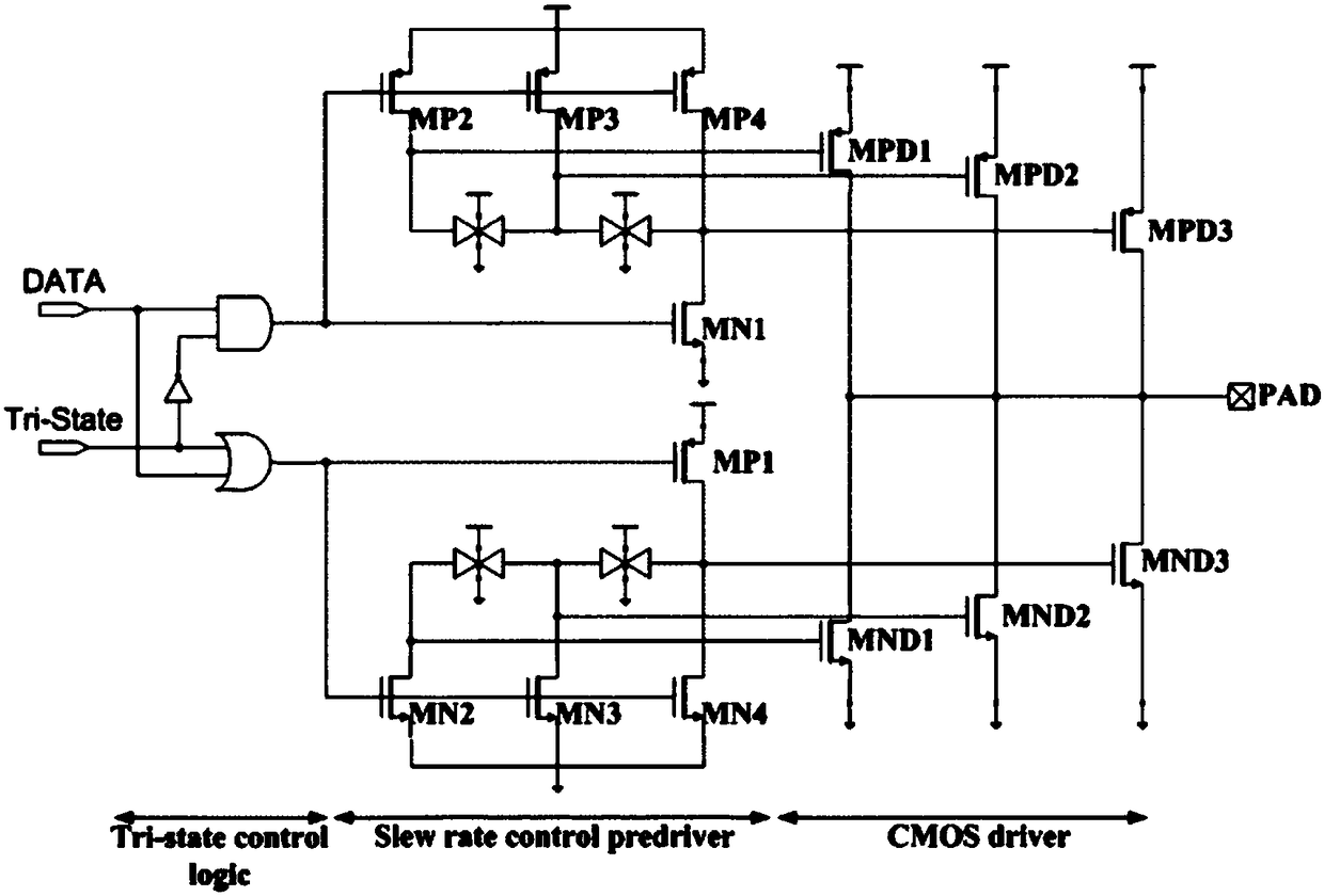
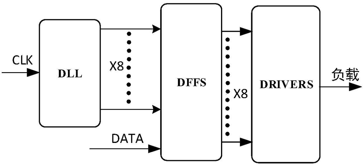
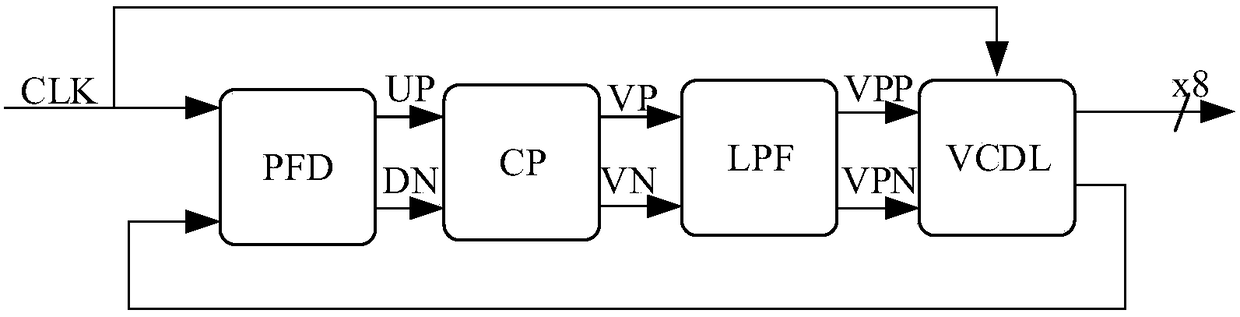
[0022] Aiming at the problem that the traditional three-state gate output signal slew rate control driver changes with the PVT, the driving capability changes greatly, resulting in a large change in the output signal slew rate. The present invention designs a CMOS driver applied to output signal slew rate control, and its driving ability does not change with process deviation, working environment temperature and power supply voltage. The present invention uses a delay phase-locked loop to generate an equal-delay signal that does not change with PVT , and then use 8 equal-delay signals for superimposition and averaging to achieve a constant rising and falling speed of the output signal jump edge, that is, to generate an output slew rate signal that does not vary with proces...


PUM


Abstract

The invention discloses a CMOS driver applied to output signal slew rate control, comprising: a delay phase locked loop DLL, a sampling circuit DFFs and a driving circuit driver which are sequentiallyconnected, wherein the delay phase locked loop comprises a phase frequency detector PFD, a charge pump circuit CP, a loop low pass filter LPF and a voltage controlled delay circuit VCDL which are sequentially connected. Compared with the typical output signal slew rate control output driver, the slew rate control provided by the invention uses an equal delay signal of the delay phase locked loop.Under the influence of PVT change, when the delay phase locked loop is locked, the phase signal clock of the delay lock phase loop maintains a constant equal interval delay, and a constant delay signal is used for superimposing to obtain a constant slew rate signal, thereby improving the defect that a large change is generated in the output signal slew rate caused by a large impact brought by thedriving capability of the conventional three-state gate slew rate control output driver due to process variations, changes in operating environment temperature, and changes in supply voltage.

Description

technical field [0001] The invention belongs to the technical field of integrated circuits, in particular to a CMOS driver applied to output signal slew rate control. Background technique [0002] The output signal slew rate of the driver is related to factors such as the driver's circuit structure, load characteristics, process deviation, working environment temperature changes, and power supply voltage changes. According to the analysis of the signal spectrum, we know that the faster the signal changes, the greater the energy of the high-frequency components contained in it, and reducing the slew rate of the transmitted signal can significantly reduce the energy of the high-frequency components contained in the signal and radiation intensity, thereby effectively reducing the electromagnetic crosstalk caused by signal radiation. With the rapid increase of the transmitted data rate today, the electromagnetic crosstalk and electromagnetic compatibility problems caused by the...

Claims


Application Information

Patent Timeline
Patent Type & Authority Applications(China)
IPC IPC(8): H03L7/081H03L7/10
CPCH03L7/0814H03L7/10
Inventor 桂小琰李凯耿莉王小力
Owner XI AN JIAOTONG UNIV
Why Eureka
Try Eureka