Sweet potato cleaning device for food processing

A food processing and cleaning device technology, applied in food processing, application, food science, etc., can solve the problems of low efficiency, incomplete, slow cleaning speed, etc., and achieve the effect of improving cleaning efficiency, sufficient cleaning, and fast cleaning

Inactive Publication Date: 2018-09-25
侯小芳
2 Cites 20 Cited by

AI-Extracted Technical Summary

Problems solved by technology

[0003] Before the sweet potato is processed, it needs to be cleaned to wash away the sediment on the surface of the sweet potato to ensure the quality ...

Method used

The working principle of the present invention is: when the present invention is in use, first sweet potato is put into cleaning frame 8, then adds clear water in water holding frame 3, until clear water submerges sweet potato, then starts the first motor 5, the second Motor 13 and the third motor 15, the third motor 15 drives the stirring shaft 16 to rotate, the stirring shaft 16 drives the stirring rod 19 to rotate, the stirring rod 19 drives the hairbrush 17 to rotate, and the silt on the sweet potato surface is brushed away, and the first motor 5 Drive the first disc 4 to rotate, the first disc 4 drives the movable rod 6 to move left and right through the cooperation of the cylindrical pin 21 and the through groove 22, the movable rod 6 drives the mounting plate 28 to move left and right through the connecting rod 23, and the mounting plate 28 passes through the T-shaped The support bar 20 drives the cleaning frame 8 to move left and right, so that the sweet potatoes in the cleaning frame 8 are...

Abstract

The invention discloses a sweet potato cleaning device for food processing. The sweet potato cleaning device comprises a bottom plate, a cleaning frame, a water containing box, a mounting plate, a driving device, a lifting plate, a second motor, a second disc, a connecting rod, a third motor, a stirring shaft, a hairbrush, a rotating shaft, a gear and a rack, wherein the driving device comprises afirst motor, a first disc, a movable rod and a connecting rod. The sweet potato cleaning device disclosed by the invention is provided with the driving device, the third motor, the stirring shaft andthe stirring rod, and the cleaning box is driven to move from the left to right by virtue of matching, so that sweet potatoes in the cleaning box continuously shake, sediments on the sweet potato surface are shaken off, and cleaning is complete. Due to the arrangement of the rotating shaft, the gear and the rack, the cleaning box continuously rotates forwards and backwards by virtue of matching,and the cleaning effect is further improved, so that cleaning is rapid and fully complete. Due to the arrangement of the second motor, the second disc and the connecting rod, the second disc is drivento rotate by the second motor, the stirring shaft and the stirring rod are driven to move up and down by virtue of matching, the cleaning is full, and the cleaning efficiency is further improved.

Application Domain

Technology Topic

Image

  • Sweet potato cleaning device for food processing
  • Sweet potato cleaning device for food processing
  • Sweet potato cleaning device for food processing

Examples

  • Experimental program(1)

Example Embodiment

[0016] The technical solutions in the embodiments of the present invention will be clearly and completely described below in conjunction with the accompanying drawings in the embodiments of the present invention. Obviously, the described embodiments are only a part of the embodiments of the present invention, rather than all the embodiments. Based on the embodiments of the present invention, all other embodiments obtained by those of ordinary skill in the art without creative work shall fall within the protection scope of the present invention.
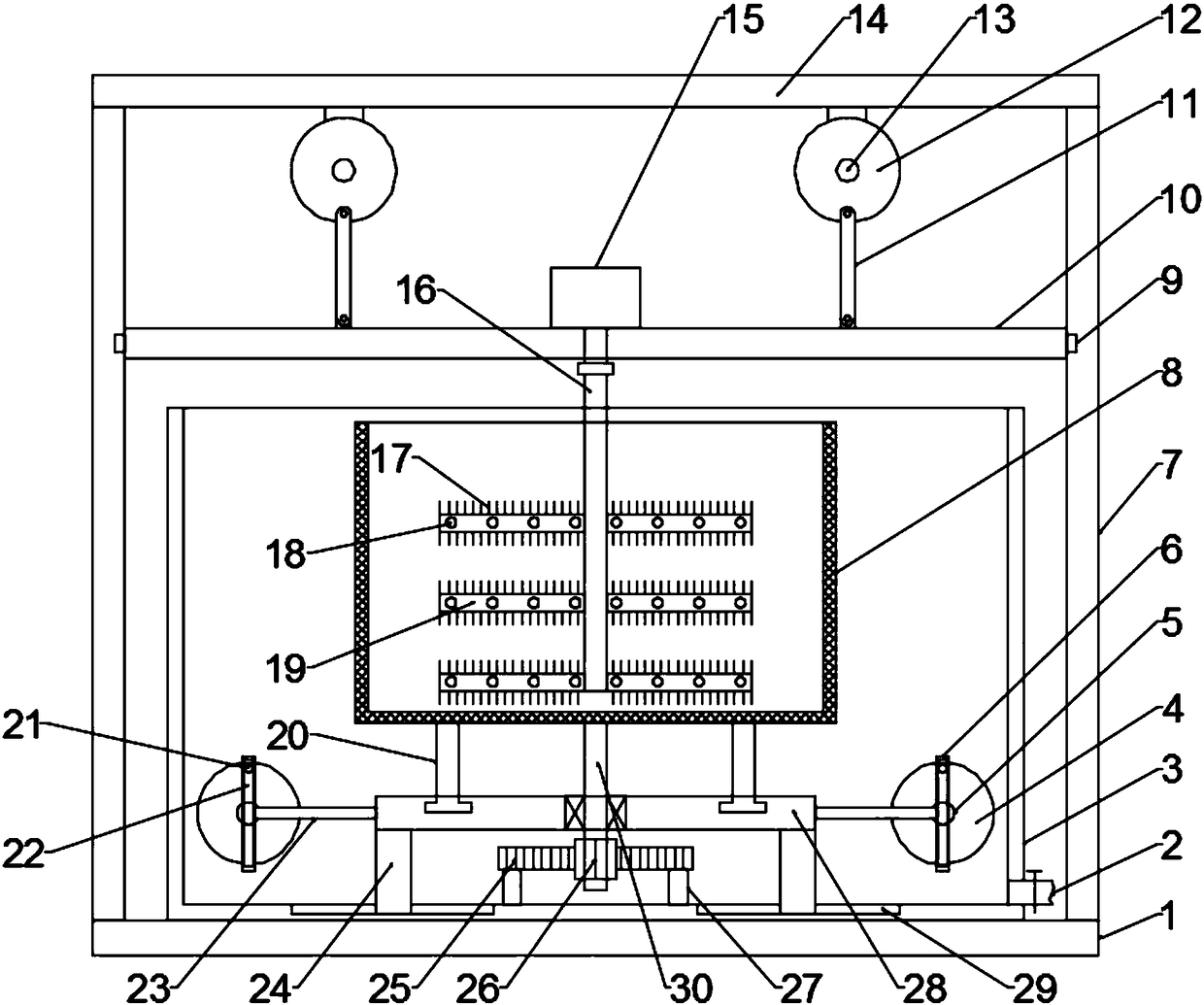
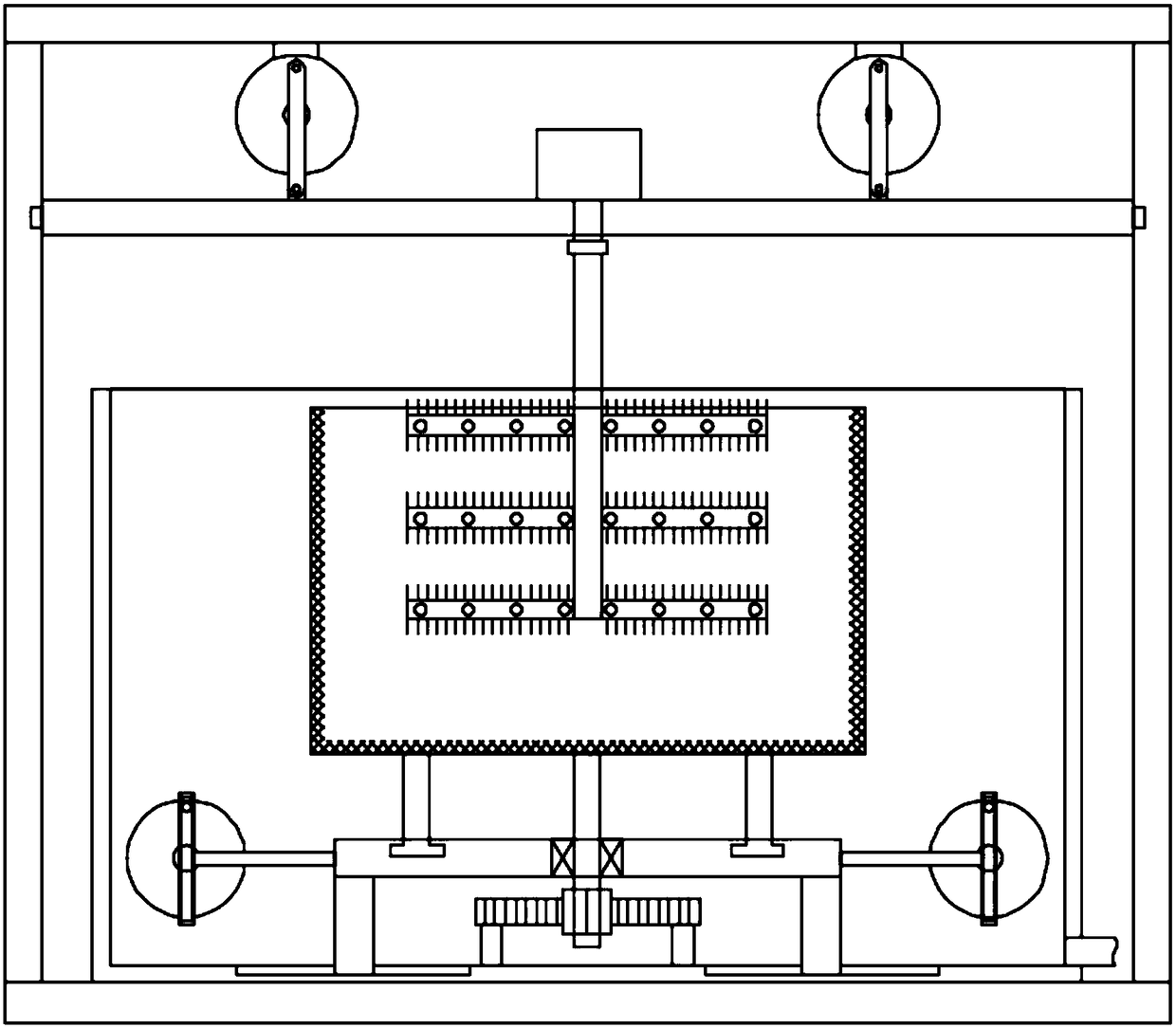
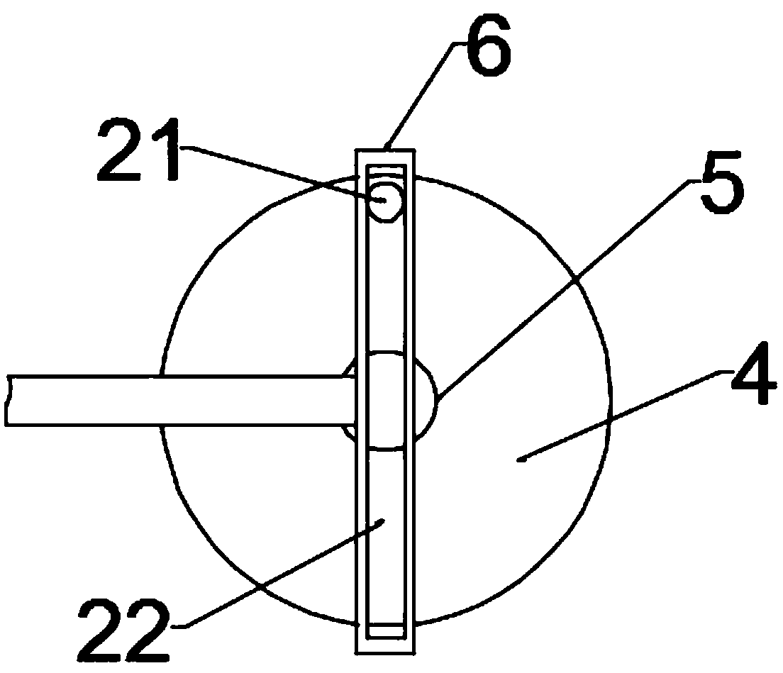
[0017] See Figure 1~3 In the embodiment of the present invention, a sweet potato cleaning device for food processing includes a bottom plate 1, a cleaning frame 8 and a water holding frame 3. The upper surface of the bottom plate 1 has a support plate 7 fixed on both sides, and the top of the support plate 7 is fixed The top plate 14 and the bottom plate 1 are fixed with a water holding frame 3 on the upper surface. The lower right of the water holding frame 3 is connected with a sewage pipe 2 and a valve is installed on the sewage pipe 2. The other end of the sewage pipe 2 is connected with external sewage treatment equipment, and the water holding frame 3 A cleaning frame 8 is provided inside. The frame wall of the cleaning frame 8 is composed of a filter screen. A mounting plate 28 is provided directly under the cleaning frame 8. Both sides of the bottom of the cleaning frame 8 are fixed with T-shaped support rods 20. The upper part of the mounting plate 28 is slidably connected. The upper part of the mounting plate 28 is provided with an annular chute that cooperates with the T-shaped support rod 20. Both sides of the bottom of the mounting plate 28 are fixed with a first sliding block 24, the first sliding block 24 and the water holding frame 3 The bottom of the inner cavity is slidably connected. The bottom of the inner cavity of the water holding frame 3 is provided with a first sliding groove 29 that is slidably fitted with the first sliding block 24. Both ends of the mounting plate 28 are provided with a driving device, and the driving device includes a first motor 5. , The first disc 4, the movable rod 6 and the connecting rod 23. The first motor 5 is installed on the outer wall of the rear side of the water holding frame 3. The end of the output shaft of the first motor 5 penetrates the rear side wall of the water holding frame 3 and extends to In the water holding frame 3, a sealing ring is connected between the output shaft of the first motor 5 and the rear side wall of the water holding frame 4, and the end of the output shaft of the first motor 5 is fixed with a first disc 4, and the first disc 4 A movable rod 6 is matedly connected to the front. A cylindrical pin 21 is fixed on the outer side of the front end surface of the first disc 4, and a through groove 22 is provided on the movable rod 6 to slide with the cylindrical pin 21. The movable rod 6 is close to the side of the mounting plate 28 A connecting rod 23 is fixed in the middle, and the other end of the connecting rod 23 is fixedly connected to the end of the mounting plate 28. A rotating shaft 30 is fixed in the middle of the bottom of the cleaning frame 8. The other end of the rotating shaft 30 penetrates the mounting plate 28 and extends below the mounting plate 28. 30 is rotatably connected to the mounting plate 28 through a bearing. A gear 26 is mounted on the shaft section of the rotating shaft 30 below the mounting plate 28. A rack 25 is provided behind the gear 26. The gear 26 meshes with the rack 25, and the rack 25 passes through a support rod 27. Fixed at the bottom of the water holding frame 3, a lifting plate 10 is arranged above the water holding frame 3, and a second sliding block 9 is fixed at both ends of the lifting plate 10, and the second sliding block 9 is slidably connected to the supporting plate 7, and the supporting plate 7 A second sliding groove slidingly fitted with the second sliding block 9 is opened on the upper part. A second motor 13 is installed on both sides of the bottom of the top plate 14. A second disc 12 is fixed at the end of the output shaft of the second motor 13. A connecting rod 11 is hinged on the outer side of the front end surface of the two discs 12, and the other end of the connecting rod 11 is hinged on the upper surface of the lifting plate 10. The middle of the upper surface of the lifting plate 10 is installed with a third motor 15 through bolts, and the output shaft of the third motor 15 passes The coupling is fixedly connected to the stirring shaft 16. The other end of the stirring shaft 16 extends into the cleaning frame 8. The surface of the shaft section of the stirring shaft 16 in the cleaning frame 8 is fixed with multiple sets of stirring rods 19 at equal intervals. The stirring rods 19 are equally spaced. A plurality of through holes 18 are provided. The through holes 18 can reduce the resistance of the stirring rod 19 and avoid the damage of the stirring rod 19. The surface of the stirring rod 19 is provided with a brush 1 circumferentially. 7.
[0018] The working principle of the present invention is: when the present invention is in use, first put the sweet potatoes into the cleaning frame 8, and then add clear water to the water containing frame 3 until the clear water floods the sweet potatoes, and then start the first motor 5, the second motor 13, and The third motor 15, the third motor 15 drive the stirring shaft 16 to rotate, the stirring shaft 16 drives the stirring rod 19 to rotate, and the stirring rod 19 drives the brush 17 to rotate to brush away the sand on the surface of the sweet potato, and the first motor 5 drives the first The disc 4 rotates, the first disc 4 drives the movable rod 6 to move left and right through the cooperation of the cylindrical pin 21 and the through groove 22, the movable rod 6 drives the mounting plate 28 to move left and right through the connecting rod 23, and the mounting plate 28 passes through the T-shaped support rod 20 Drive the cleaning frame 8 to move left and right, so that the sweet potatoes in the cleaning frame 8 are constantly swaying, which is beneficial to shake off the surface of the sweet potatoes and make the cleaning more thorough. At the same time, the cleaning frame 8 drives the shaft 30 and the gears 26 on it when the cleaning frame 8 moves from side to side. The gear 26 engages with the rack 25 to drive the rotating shaft 30 and the cleaning frame 8 fixedly connected to the rotating shaft 30 to continue forward and reverse, which further improves the cleaning effect and makes the cleaning more rapid and thorough. At the same time, the second motor 13 drives the second The disc 12 rotates, the second disc 12 drives the lifting plate 10 up and down through the connecting rod 11, and the lifting plate 10 drives the third motor 15 to move up and down. The third motor 15 drives the stirring shaft 16 and the stirring rod 19 to move up and down. It is sufficient to further improve the cleaning efficiency. After the cleaning is completed, the sewage is discharged from the sewage pipe 2, and then the sweet potatoes are taken out from the cleaning frame 8.
[0019] For those skilled in the art, it is obvious that the present invention is not limited to the details of the foregoing exemplary embodiments, and the present invention can be implemented in other specific forms without departing from the spirit or basic characteristics of the present invention. Therefore, from any point of view, the embodiments should be regarded as exemplary and non-limiting. The scope of the present invention is defined by the appended claims rather than the foregoing description, and therefore it is intended to fall within the claims. All changes within the meaning and scope of equivalent elements of are included in the present invention. Any reference signs in the claims should not be regarded as limiting the claims involved.
[0020] In addition, it should be understood that although this specification is described in accordance with the implementation manners, not each implementation manner only includes an independent technical solution. This narration in the specification is only for clarity, and those skilled in the art should consider the specification as a whole The technical solutions in the embodiments can also be appropriately combined to form other implementations that can be understood by those skilled in the art.

PUM

no PUM

Description & Claims & Application Information

We can also present the details of the Description, Claims and Application information to help users get a comprehensive understanding of the technical details of the patent, such as background art, summary of invention, brief description of drawings, description of embodiments, and other original content. On the other hand, users can also determine the specific scope of protection of the technology through the list of claims; as well as understand the changes in the life cycle of the technology with the presentation of the patent timeline. Login to view more.

Similar technology patents

Classification and recommendation of technical efficacy words

  • Improve cleaning effect
  • Quick wash

Collar and cuff cleaning device

InactiveCN103882655AQuick washMake sure it looks like newBrushing washing machinesBrush bodiesEngineeringMechanical engineering
Owner:姜博仑

Press filter

InactiveCN105413268AQuick washIncrease squeezeFiltration separationPistonEngineering
Owner:HENAN BAIHUI ENVIRONMENTAL PROTECTION TECH CO LTD

Insulator water-washing device and robot

Owner:ELECTRIC POWER RESEARCH INSTITUTE OF STATE GRID SHANDONG ELECTRIC POWER COMPANY +2
Why Eureka
Try Eureka