
Method for evaluating road technical condition based on non-destructive testing technique

A technology for non-destructive testing of technical conditions, applied in radio wave measurement systems, radio wave reflection/re-radiation, measurement devices, etc., can solve the problems of long single operation time, stuck drill, affecting driving safety, etc., to achieve the degree of equipment automation High, meet the requirements of precision, and improve the effect of detection efficiency

Inactive Publication Date: 2018-09-25
CHANGSHA UNIVERSITY OF SCIENCE AND TECHNOLOGY
View PDF7 Cites 10 Cited by
  • Summary
  • Abstract
  • Description
  • Claims
  • Application Information

AI Technical Summary

Problems solved by technology

Improper repair or filling will affect driving comfort on the one hand, and seriously affect driving safety; on the other hand, rainfall on the road surface will penetrate into the base and soil foundation along the drill core sampling site, causing more serious consequences
[0007] (2) Low efficiency and high cost
Drilling core sampling is affected by many factors, a single operation time is long, the speed is slow, continuous operation and detection cannot be performed, and there are extremely high requirements for manpower and material resources; the length of the core sample is limited by the conditions of the core drilling machine, and improper operation is prone to occur Drill stuck, core sample cannot be taken out, etc.
In addition, the noise is also a major disadvantage
[0008] (3) Poor representation
Manual on-site naked eye observation is inefficient and dangerous, and cannot fully detect road sections with large traffic volumes; vehicle-mounted road surface damage collection systems are currently mostly used for evaluation of road surface cracks, ruts, flatness and other indicators to evaluate the use of roads Performance, auxiliary core sampling is used as a reference for road maintenance efforts. On the one hand, the reference index is too single, and the representativeness of core sampling is poor, which cannot guide the road maintenance efforts in the later stage. The combination of other road non-destructive testing techniques and equipment weakens the credibility of the system as a reference indicator

Method used


Image

  • Method for evaluating road technical condition based on non-destructive testing technique
  • Method for evaluating road technical condition based on non-destructive testing technique
  • Method for evaluating road technical condition based on non-destructive testing technique

Examples


Embodiment Construction

[0021] In order to better understand the present invention, the present invention will be further described in detail below in conjunction with the accompanying drawings and specific embodiments. The described embodiments are only used to illustrate the technical solutions of the present invention, and are not intended to limit the present invention.

[0022] First use the intelligent road surface damage automatic collection system to collect road surface images, refer to figure 1 shown. Step 1, perform distance calibration and distance correction; Step 2, image acquisition; Step 3, compress and store the image; Step 4, analyze and classify and mark the collected images, and record the test location; Step 5, export data.

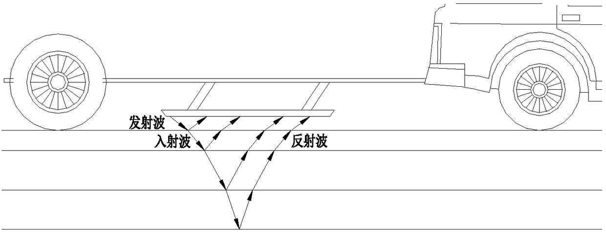
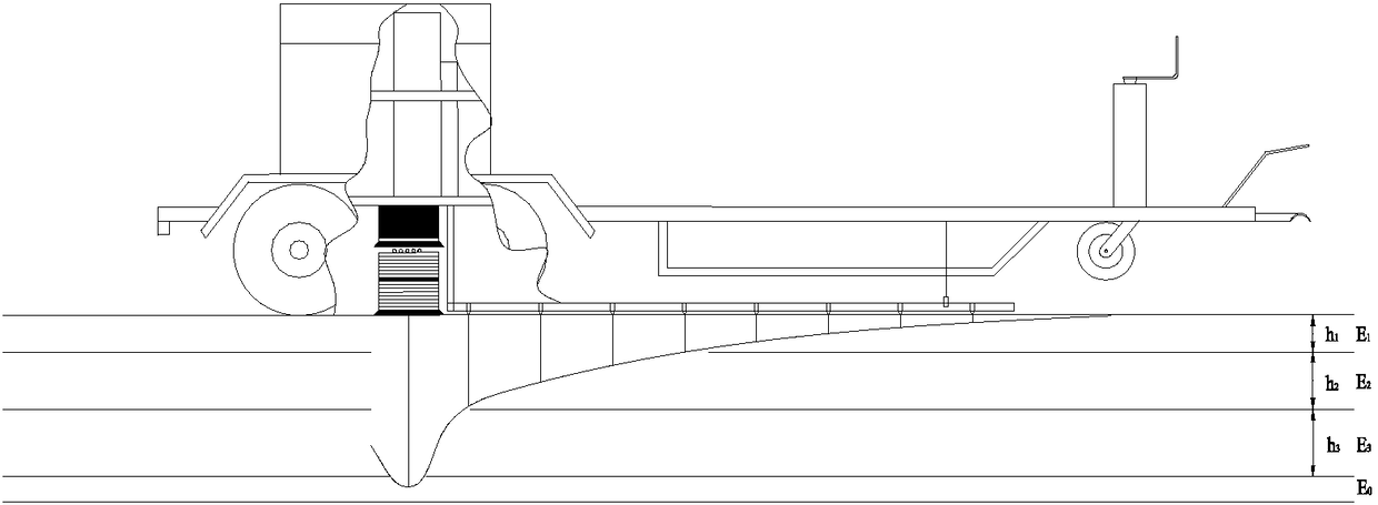
[0023] Then use 3D ground penetrating radar to collect data inside the pavement structure, refer to figure 2 shown. Step 1, radar rangefinder calibration; Step 2, radar basic parameter setting; Step 3, radar equipment automatic detection; Step 4, data acq...


PUM


Abstract

The invention discloses a method for evaluating a road technical condition based on a non-destructive testing technique. The method includes performing road surface image collection by utilizing an intelligent road surface damage automatic collection system; performing data collection on the inside of the pavement structure by utilizing 3D ground penetrating radar; subjecting the images collectedby the intelligent road surface damage automatic collection system to manual or intelligent analysis; processing data, collected by the 3D ground penetrating radar, of the inside of the pavement structure; comparing the data collected by the intelligent road surface damage automatic collection system with the image data collected by the 3D ground penetrating radar; detecting positions, abnormal inimages collected by the 3D ground penetrating radar, by a falling weight deflectometer again; estimating whether the pavement structure is damaged or not according to a pavement structure modulus andcarrying capacity; performing comparison with the images collected by the 3D ground penetrating radar to determine the specific location of damage inside the pavement structure; and sampling and drilling a core sample to verify accuracy of a detection result, and giving a scientific evaluation of the road technical condition and a reasonable maintenance plan.

Description

technical field [0001] The invention belongs to the technical field of road engineering, and relates to a method for evaluating road technical conditions based on non-destructive testing technology. Background technique [0002] Ground-penetrating radar transmits high-frequency electromagnetic waves to the ground through the transmitting antenna, and receives the electromagnetic waves reflected back to the ground through the receiving antenna. Characteristics such as waveform, amplitude strength, and temporal variation infer the spatial location, structure, morphology, and burial depth of subsurface media. Ground-penetrating radar detection has the advantages of fast, non-destructive, continuous detection, high resolution, and reliable detection quality. promote. 3D ground-penetrating radar is based on two-dimensional ground-penetrating radar, which realizes real-time three-dimensional display of test data and analysis results. It can display longitudinal section, cross-se...

Claims


Application Information

Patent Timeline
IPC IPC(8): G01N33/42G01S13/86G01S13/88
CPCG01N33/42G01S13/867G01S13/885
Inventor 李盛马永波房硕刘萌杨帆范萌萌
Owner CHANGSHA UNIVERSITY OF SCIENCE AND TECHNOLOGY
Learn More