
Film exposure table for glass production

A technology of exposure table and film, which is applied in the field of exposure table, can solve the problems of uneven illumination, temperature rise, image deformation, etc., and achieve the effect of improving exposure efficiency, high exposure efficiency, and low energy consumption

Pending Publication Date: 2018-09-25
XUCHANG FUHUA GLASS
View PDF0 Cites 1 Cited by
  • Summary
  • Abstract
  • Description
  • Claims
  • Application Information

AI Technical Summary

Problems solved by technology

[0002] Exposure is to cover the mask plate on the glass surface coated with photoresist, and use exposure lamp to irradiate; to make the photoresist in the light-receiving part react chemically, and change the solubility of this part of the glue in the developer, so after development, the photoresist film It shows the same pattern as on the mask plate. In the prior art, film is mainly used as the mask plate, and there are mainly the following problems: first, the illumination is not uniform, so that the degree of illumination received on the coated glass is also inconsistent. The degree of chemical reaction of the photoresist in the light-receiving part is also inconsistent; secondly, when the exposure lamp is working, there is a situation in which electrical energy is converted into heat energy, which makes the temperature of the exposure room and the exposure table rise, and a cooling device is required to cool the exposure room and the exposure table. Cooling, the existing cooling device is fixed, and it is impossible to uniformly cool down each area of ​​the exposure chamber and the exposure table, resulting in uneven heating of the original on the exposure table, resulting in deformation of the image on the film, and the yield rate of the exposure process cannot be guaranteed; Therefore, in order to solve the above problems, it is necessary to develop a film exposure station for glass production.

Method used


Image

  • Film exposure table for glass production
  • Film exposure table for glass production

Examples


Embodiment Construction

[0013] The technical solution of the present invention will be further specifically described below in conjunction with the accompanying drawings.

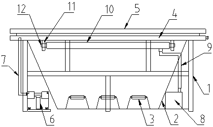
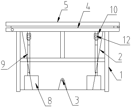
[0014] Such as figure 1 , figure 2 As shown, a film exposure table for glass production includes a frame 1, a conical light box 2, an exposure lamp 3, an exposure platform 4, a cover plate 5, a vacuum pump 6, a vacuum air pipe 7, a cooling machine 8, a cooling pipe 9 and an outlet Wind device 10 .

[0015] Wherein, a conical light box 2 is arranged on the frame 1, and an exposure lamp 3 is arranged in the conical light box 2. Preferably, there are three exposure lamps 3, and an exposure platform 4 is arranged on the frame 1 above the conical light box 2. The platform 4 is provided with a cover plate 5, one side of the cover plate 5 and one side of the exposure platform 4 are hinged together, the exposure platform 4 and the cover plate 5 form a cavity for accommodating the object to be exposed, and the cover plate 5 is covered w...


PUM


Abstract

The invention discloses a film exposure table for glass production. The film exposure table comprises a frame, a tapered lamp box, exposure lamps, an exposure platform, a cover plate, a vacuum pump, avacuum air pipe, a cooling machine, a cooling pipeline and an air outlet device, wherein the tapered lamp box is arranged on the frame, the exposure lamps are arranged in the tapered lamp box, the exposure platform is arranged at the position, above the tapered lamp box, on the frame, the cover plate is arranged on the exposure platform, a cavity for accommodating an exposed object is defined bythe exposure platform and the cover plate, packing cloth is arranged on the cover plate in a covering manner, a sealing strip is arranged at the position of the edge of the inner side of the cover plate, the vacuum pump is arranged on the frame, and is connected with the interior of a sealing cavity formed by the cover plate and an exposure slip through the vacuum air pipe, the cooling machine isarranged on the frame, and is connected with the air outlet device through the cooling pipeline, and the air outlet device is arranged at the upper parts of the two sides in the tapered lamp box. In general, the film exposure table has the advantages of being uniform in illumination, uniform and complete in cooling, low in energy loss, and high in exposure efficiency.

Description

technical field [0001] The invention relates to an exposure platform, in particular to a film exposure platform for glass production. Background technique [0002] Exposure is to cover the mask plate on the glass surface coated with photoresist, and use exposure lamp to irradiate; to make the photoresist in the light-receiving part react chemically, and change the solubility of this part of the glue in the developer, so after development, the photoresist film It shows the same pattern as on the mask plate. In the prior art, film is mainly used as the mask plate, and there are mainly the following problems: first, the illumination is not uniform, so that the degree of illumination received on the coated glass is also inconsistent. The degree of chemical reaction of the photoresist in the light-receiving part is also inconsistent; secondly, when the exposure lamp is working, there is a situation in which electrical energy is converted into heat energy, which makes the temperat...

Claims


Application Information

Patent Timeline
IPC IPC(8): G03F7/20
CPCG03F7/70008G03F7/70891
Inventor 寇红龙朱建军
Owner XUCHANG FUHUA GLASS
Learn More