Paper pulp stirring device for papermaking
A stirring device and pulp technology, which is used in mixers with rotary stirring devices, transportation and packaging, mixers, etc., can solve the problems of long stirring time, uneven density, and insufficient stirring, and achieve uniform stirring and shorten production. Cycle time, the effect of improving production efficiency
- Summary
- Abstract
- Description
- Claims
- Application Information
AI Technical Summary
Problems solved by technology
Method used
Image

Examples
Embodiment Construction
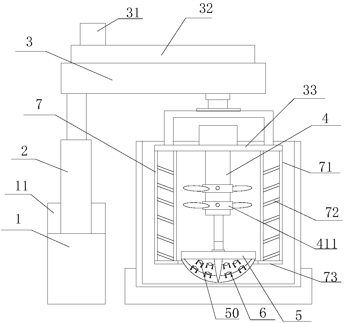
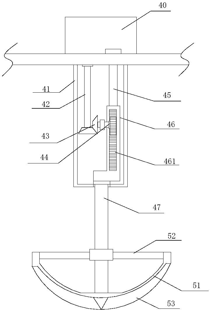
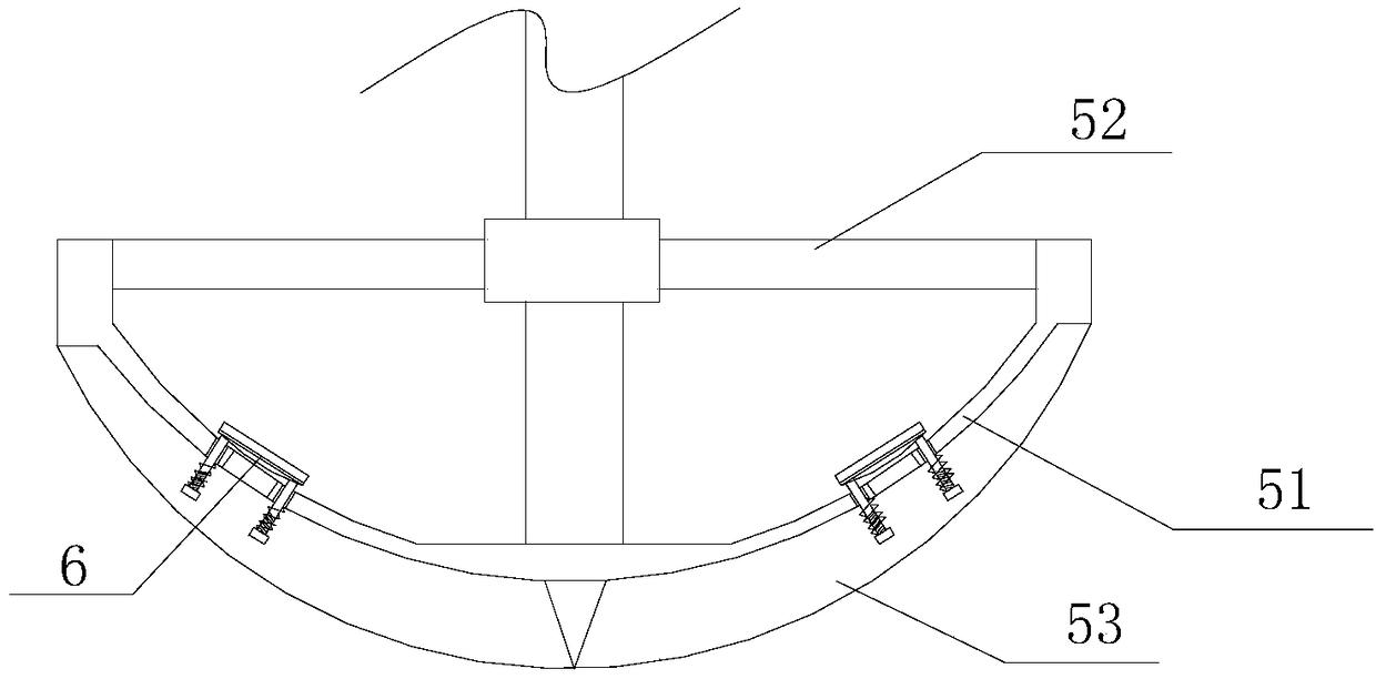
[0017] refer to Figure 1 to Figure 5 A pulp stirring device for papermaking according to the present invention comprises a base 1, a supporting telescopic shaft 2, a driving seat 3, a lifting drive mechanism 4, a material lifting and mixing mechanism 5, a driving blocking assembly 6 and a fixed stirring mechanism 7, the base 1 is equipped with a supporting telescopic shaft 2, and the supporting telescopic shaft 2 is provided with a drive base 3, and the drive base 3 is connected with a drive disc 33 through a drive shaft, and a lifting drive mechanism is provided at the center below the drive disc 33 4. Several stirring blade assemblies 411 are installed on the lifting drive mechanism 4, and a material lifting and mixing mechanism 5 is installed under the lifting driving mechanism 4, and several slurry feeding channels are opened on the lifting and mixing mechanism 5 50, the drive block assembly 6 is installed on the material lifting and mixing mechanism 5 through a spring, t...
PUM
 Abstract
Description
Claims
Application Information
 - R&D
- Intellectual Property
- Life Sciences
- Materials
- Tech Scout
- Unparalleled Data Quality
- Higher Quality Content
- 60% Fewer Hallucinations
Browse by: Latest US Patents, China's latest patents, Technical Efficacy Thesaurus, Application Domain, Technology Topic, Popular Technical Reports.
© 2025 PatSnap. All rights reserved.Legal|Privacy policy|Modern Slavery Act Transparency Statement|Sitemap|About US| Contact US: help@patsnap.com