A splitting and shearing machine for processing the protective cover of the steel belt of the transmitting antenna

A technology of transmitting antenna and protective cover, applied in the field of machinery, can solve the problems of limited cutting thickness, inconvenient tool change, waste of time, etc., achieve the effect of convenient tool change, improve cutting efficiency, and prevent movement

Active Publication Date: 2019-11-29
浙江联品电子科技有限公司
View PDF6 Cites 0 Cited by
  • Summary
  • Abstract
  • Description
  • Claims
  • Application Information

AI Technical Summary

Problems solved by technology

[0003] The current dividing shears are mostly circular saw cutters, the cutting thickness is limited, and it is very inconvenient to change the cutters. It is troublesome to adjust the distance between the cutters. It is necessary to use measuring tools to measure, which is a waste of time.

Method used


Image

  • A splitting and shearing machine for processing the protective cover of the steel belt of the transmitting antenna
  • A splitting and shearing machine for processing the protective cover of the steel belt of the transmitting antenna
  • A splitting and shearing machine for processing the protective cover of the steel belt of the transmitting antenna

Examples


Embodiment Construction

[0027] The following are specific embodiments of the present invention and the technical solution of the present invention will be further described in conjunction with the accompanying drawings.

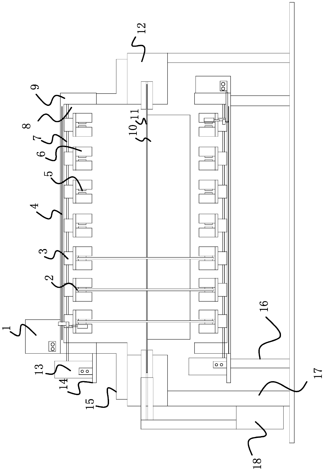
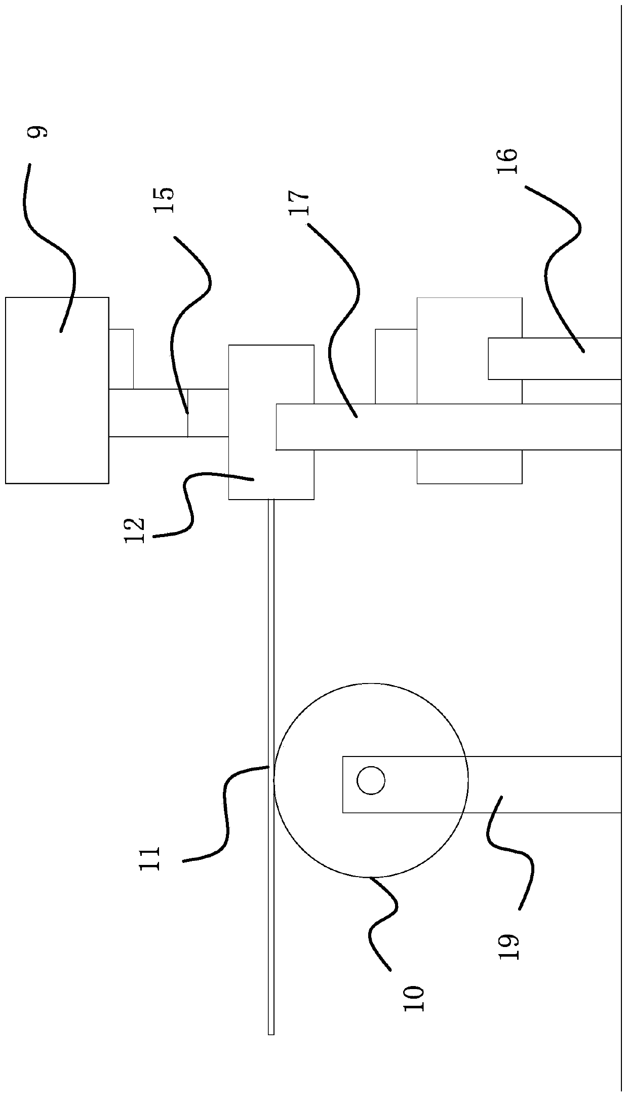
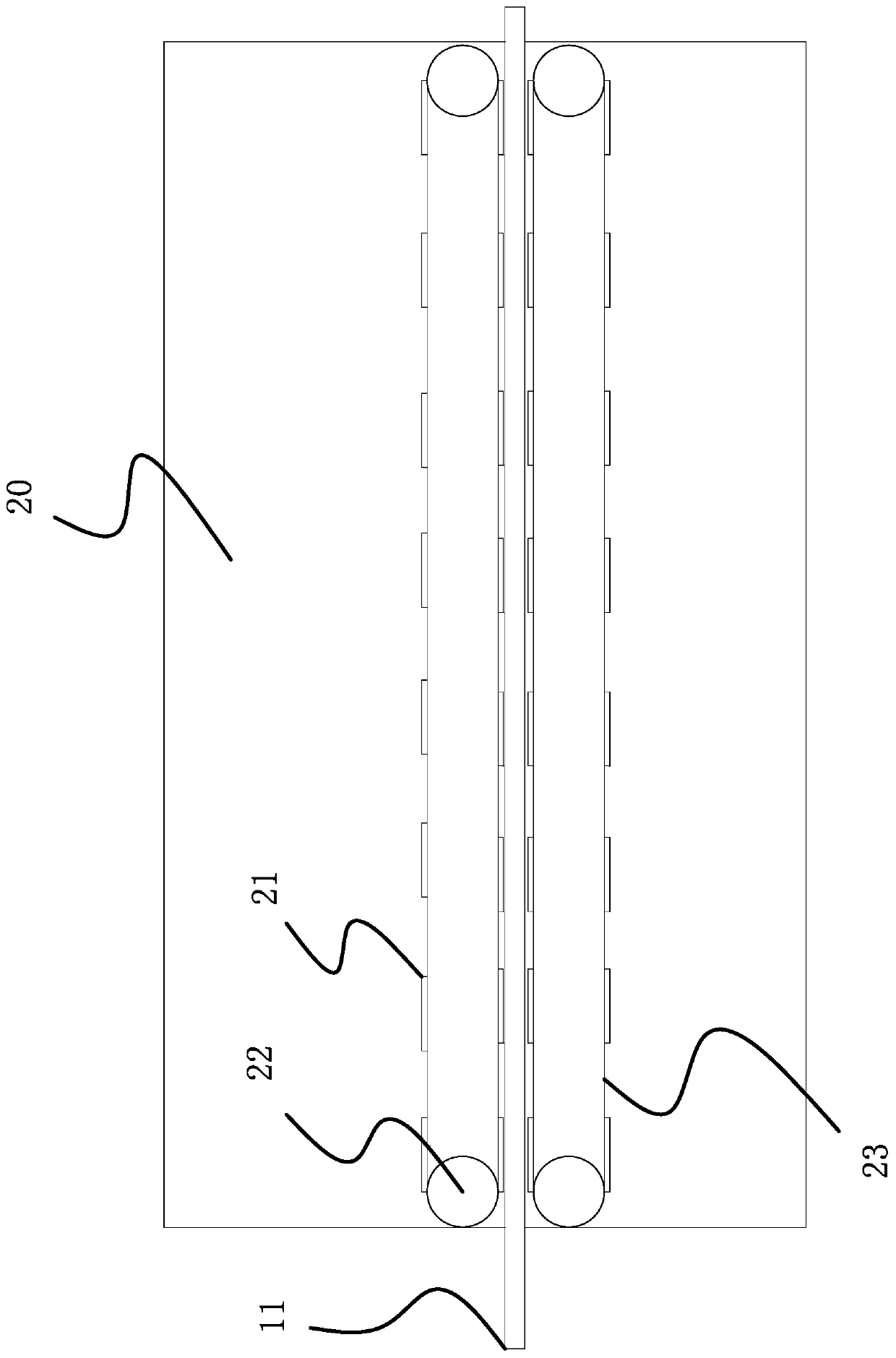
[0028] Such as figure 1 , figure 2 , Figure 4 and Figure 6 As shown, a cutting machine for processing the protective sleeve of the transmitting antenna steel band, it includes a knife group mechanism, a traction mechanism 12 and a feed roller 10, and it is characterized in that the knife group mechanism includes a circular saw blade 2, a motor, a hydraulic pressure Pump 13, hydraulic fixed roller 7 and knife group seat 9, knife group seat 9 has two sets, is mirror image setting up and down, has some clamping parts 6 and sliding part 3 on the knife group seat 9, knife group seat 9 is square, knife group There is a mounting plate 14 on the outer side of the group seat 9, a scale line 4 is provided on the outside of the knife group seat 9, a strip groove 8 is provided at the bott...


PUM


Abstract

The invention provides a shearing machine for machining a protective sleeve of a steel strip of a transmitting antenna. The shearing machine is characterized in that a cutter group mechanism comprisesannular saw blades, a motor I, a hydraulic pump, a hydraulic fixed roller and two sets of cutter group seats, wherein the cutter group seats are arranged in an up-down mirror image mode, the cutter group seats are provided with a plurality of clamping parts and a plurality of sliding parts and are in a square shape, and strip-shaped grooves are formed in the bottoms of the cutter group seats; each clamping part is internally provided with two rotating wheels, the end portions of each of the annular saw blades are clamped between two corresponding rotating wheels, and the annular saw blades are driven by the rotating wheels to operate; the clamping parts are internally provided with concave shrapnels, and two ends of the concave shrapnels abut against the rotating wheels and apply the force to enable the rotating wheels to get close to each other; the clamping parts are provided with buttons, clamping blocks are connected to the inner ends of the buttons, the clamping blocks abut against the two end faces of the concave shrapnels, and the concave shrapnels are propped to open by the clamping blocks under pushing of the buttons; and the sliding parts are fixedly connected to the clamping parts. When the annular saw blades are installed, just the buttons on the clamping parts are pressed, the end portions of the annular saw blades are put at the rotating wheels after the rotatingwheels are released, and tool changing can be completed by releasing the buttons, so that tool changing is convenient.

Description

technical field [0001] The invention belongs to the technical field of machinery, and relates to a splitting and shearing machine for processing a steel strip protective cover of a transmitting antenna. Background technique [0002] The transmitting antenna is easy to break under bad weather conditions, such as typhoon blown off, or being crushed by ice and snow. At this time, a protective cover is needed to support it. The protective cover is wrapped around the transmitting antenna by a steel belt. The steel strip is processed by a shearing machine. The main function of the shearing machine is to cut the wide roll material into a narrow coil of a certain size in the length direction. Here, it is used to cut the steel strip into the width and structure required by the manufacturer. It is roughly the feeding roller for conveying the steel belt, the roller and the tractor on the outer surface that can be equipped with knives. [0003] Most of the current dividing shears are c...

Claims


Application Information

Patent Timeline
Patent Type & Authority Patents(China)
IPC IPC(8): B23D57/00B23D59/00
CPCB23D57/00B23D59/00
Inventor 王永森张思林周松
Owner 浙江联品电子科技有限公司
Why Eureka
Try Eureka