Log high frequency vacuum drying tank

A vacuum drying and high-frequency technology, applied in wood heating, wood treatment, wood treatment details, etc., can solve problems such as low efficiency, increased processing energy consumption, and inability to effectively use limited space, so as to ensure the stability of use and prevent The effect of overloading

Active Publication Date: 2021-06-08
CHENGDU ZINAN FURNITURE
View PDF5 Cites 0 Cited by
  • Summary
  • Abstract
  • Description
  • Claims
  • Application Information

AI Technical Summary

Problems solved by technology

The reason is that when drying wood, ordinary drying tanks cannot effectively use its limited space, and the drying efficiency is low, and secondary drying treatment is required, which increases the processing energy consumption again.

Method used


Image

  • Log high frequency vacuum drying tank
  • Log high frequency vacuum drying tank
  • Log high frequency vacuum drying tank

Examples


Embodiment 1

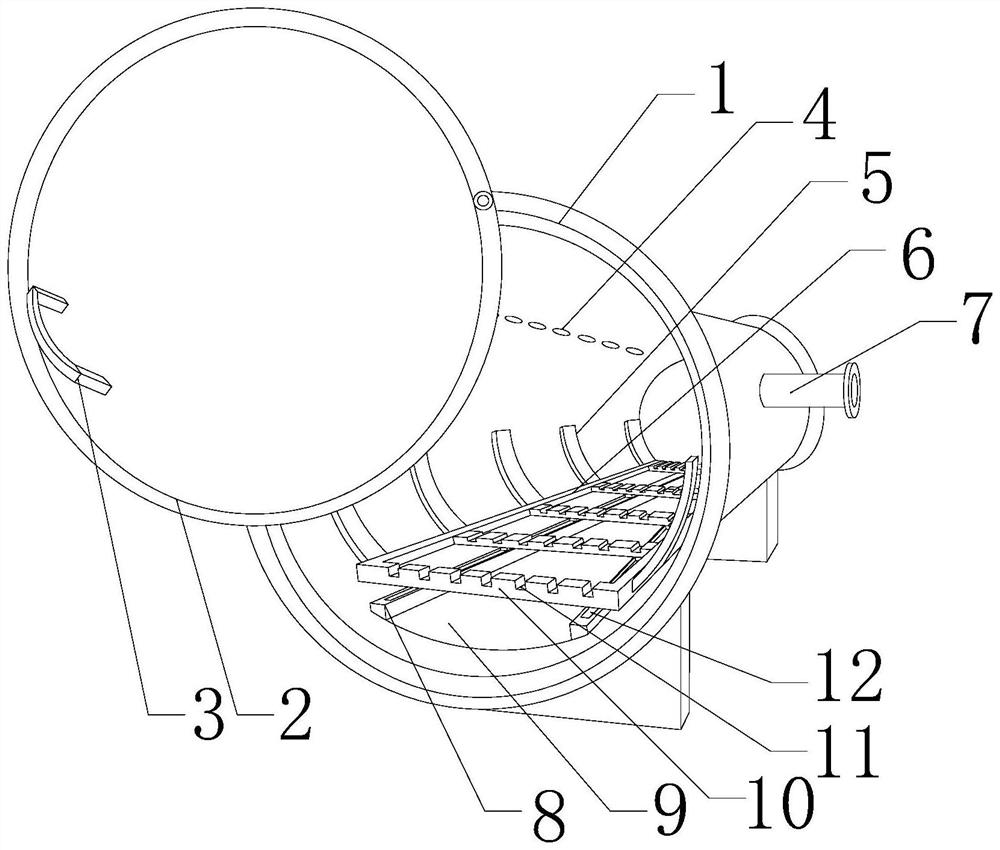
[0030] Such as figure 1 , 3 , 4, and 5, the present embodiment includes a tank body 1 and an end cap 2 for closing the tank body 1, a liquid collecting groove 9 is opened on the inner wall of the bottom of the tank body 1 along the axis of the tank body, and the liquid collecting tank 9 The two ends of the groove 9 are respectively provided with guide rails 8 parallel to the axis of the tank body 1, and a slide groove 12 is provided on the upper surface of each guide rail 8, and a plurality of grooves are opened on the inner wall of the top along the axis of the tank body 1. A suction hole 4, and a plurality of suction holes 4 communicate with the suction pipe 7 arranged on the outer wall of the tank body 1, and a heating assembly is arranged on the outer wall of the tank body 1 along the circumferential direction; A rectangular bracket formed by splicing two transverse plates 6 and two longitudinal plates 10, and has a card slot 11 on the upper surface of each of the longitu...

Embodiment 2

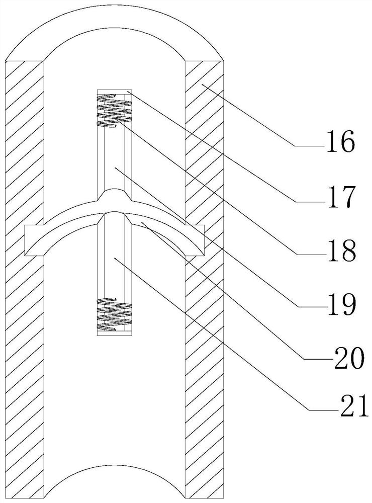
[0035] Such as Figure 1~4 As shown, in this embodiment, a limit cylinder 16 is provided on the top outer wall of the tank body 1 along the axial direction, a heat insulating base is provided on the upper surface of the tank body 1, and the cylinder 22 is arranged above the tank body 1 on the heat insulating base. , the pin 13 is connected with the inner side wall of the end cover 2 through a universal ball, and a through hole is opened on the top outer wall of the tank body 1, the pin 13 moves through the through hole, and the limit tube 16 is connected with the cylinder 22 The output end is connected, and a radial groove 20 is opened on the inner peripheral wall of the limit cylinder 16 along the circumferential direction, and a block 15 matching the radial groove 20 is provided on the outer peripheral wall of the pin 13, An active groove I19 communicating with the radial groove 20 is formed on the inner wall of the limiting cylinder 16 away from the end cover 2 , and the mo...

Embodiment 3

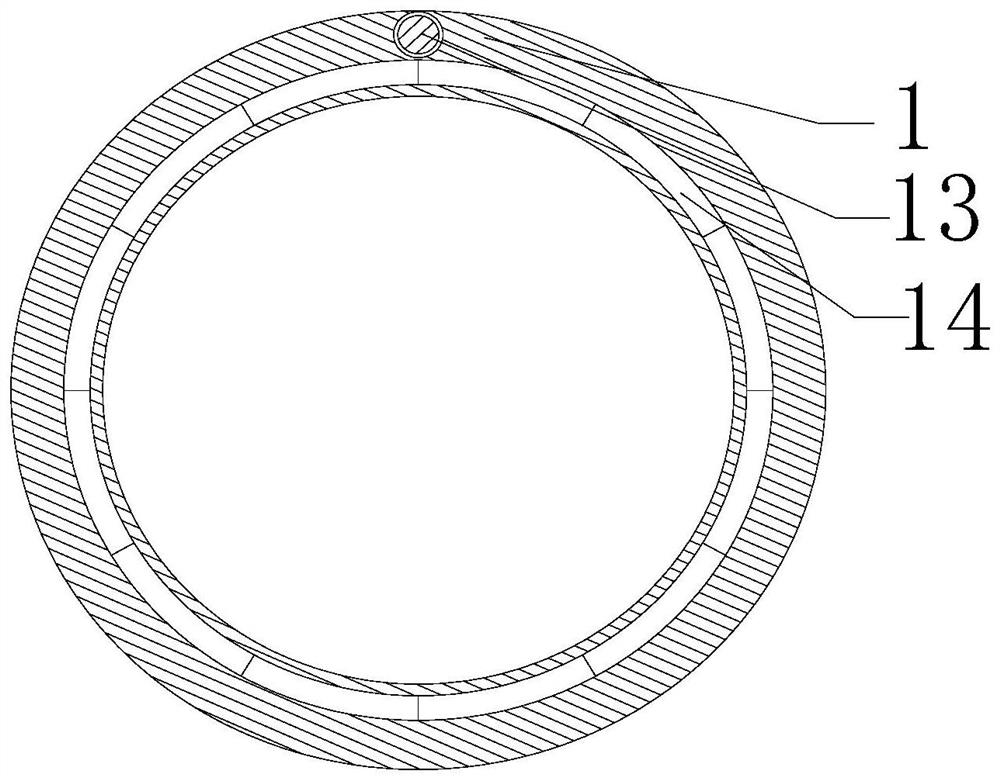
[0040] Such as Figure 1~4 As shown, in this embodiment, a plurality of butt joint grooves 14 are provided on the open end surface of the tank body 1 along the circumference thereof, a rubber ring is provided on the inner side wall of the end cover 2, and a rubber ring is provided on the rubber ring. A plurality of rubber protrusions matched with the docking groove 14 . Further, since the tank body 1 is always in an airtight state during the drying process, and the end cap 2 is a movable part, the applicant provided a rubber ring on the inner side wall of the end cap 2, and at the same time along the circumferential direction of the rubber ring in its The inner wall is provided with a plurality of rubber protrusions, and the open end face of the tank body 1 is provided with a plurality of butt grooves 14 matched with the rubber protrusions, that is, when capping, through a plurality of rubber protrusions and rubber rings, the A plurality of different sealing sections are form...


PUM


Abstract

The invention discloses a high-frequency vacuum drying tank for logs, which includes a tank body and an end cover, and a liquid collection tank is opened on the inner wall of the bottom along the axis of the tank body, and guide rails are respectively arranged at both ends of the liquid collection tank, and each guide rail There is a chute on the upper surface, and a plurality of suction holes are opened on the inner wall of the top along the axis of the tank body. The plurality of suction holes communicate with the suction pipes arranged on the outer wall of the tank body. A heating assembly is arranged on the outer wall; a card slot is opened on the upper surface of each longitudinal plate, and a plurality of sliding blocks are arranged in the middle of the lower surface of each transverse plate. The invention heats the log in a vacuum environment, and discharges the steam inside the tank in time to ensure that the wood inside the tank is heated evenly, the drying degree of the wood in different positions is consistent, and at the same time, the drying heat efficiency of the wood is guaranteed to be the same as that of drying The cost is positively correlated and the thermal efficiency of the drying tank is maximized while drying the wood.

Description

technical field [0001] The invention relates to the field of log processing, in particular to a high-frequency vacuum drying tank for logs. Background technique [0002] Timber needs to go through many processes from log to final product. Wood drying is to ensure the quality of wood and wood products and prolong the service life. Appropriate measures must be taken to reduce the moisture (moisture content) in the wood to a certain extent. . As a large energy consumer in the wood processing industry, wood drying accounts for 40-70% of wood processing energy consumption, and the thermal efficiency of drying is generally low, usually only between 30-40%; in addition, the pollution caused by the drying process is often It is an important source of environmental pollution in China. Taking the steam drying workshop with an annual drying capacity of 10,000 cubic meters as an example, the harmful substances discharged per hour are about 40Kg of smoke and dust, 1900 cubic meters of c...

Claims


Application Information

Patent Timeline
Patent Type & Authority Patents(China)
IPC IPC(8): B27K5/00
CPCB27K5/001
Inventor 黄宪婷
Owner CHENGDU ZINAN FURNITURE
Why Eureka
Try Eureka