Equalization circuit realizing parallel charging and selective single cell battery equalization discharge and control method thereof

A single battery and equalizing circuit technology, applied in battery/fuel cell control devices, charging stations, electric vehicle charging technology, etc., can solve the problem of inconsistent battery energy, and achieve high equalization efficiency, easy control, and convenient circuit structure. Effect

Active Publication Date: 2018-09-28
KUNMING UNIV OF SCI & TECH
View PDF10 Cites 13 Cited by
  • Summary
  • Abstract
  • Description
  • Claims
  • Application Information

AI Technical Summary

Problems solved by technology

[0004] Aiming at the problem of energy inconsistency between a large number of lithium-ion single batteries connected in series in the vehicle-mounted lithium-ion power battery system of electric vehicles, the present invention provides an equalization circuit for parallel charging and selective single-cell discharge equalization and a control method thereof

Method used


Image

  • Equalization circuit realizing parallel charging and selective single cell battery equalization discharge and control method thereof
  • Equalization circuit realizing parallel charging and selective single cell battery equalization discharge and control method thereof
  • Equalization circuit realizing parallel charging and selective single cell battery equalization discharge and control method thereof

Examples


Embodiment 1

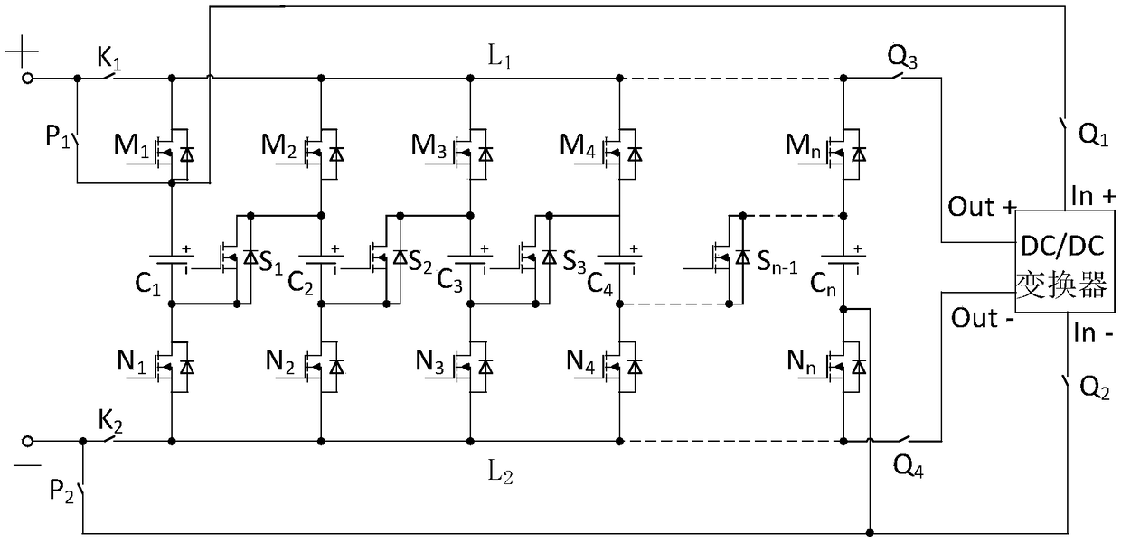
[0024] Embodiment 1: as figure 1 As shown, an equalization circuit for parallel charging and selective single battery discharge equalization consists of a battery pack, a DC / DC converter, a Mosfet switch with an antiparallel diode, and a bus switch K 1 , bus switch K 2 , bus switch P 1 , bus switch P 2 , switch Q 1 , switch Q 2 , switch Q 3 , switch Q 4 constitute;

[0025] The battery pack consists of n single cells C i Composed of, the Mosfet switch with anti-parallel diode is composed of n Mosfet switches M with anti-parallel diode i , n Mosfet switches with antiparallel diodes N i , n-1 Mosfet switches S with antiparallel diodes j Composition; wherein, j=1,2,3...,n-1, i=1,2,3...,n;

[0026] The single battery C i The anode of the Mosfet switch M with an antiparallel diode i connected to the source of the Mosfet switch with an antiparallel diode M i The drain of the battery pack is connected to the positive bus L 1 on and by the bus switch K 1 , bus switch P...

Embodiment 2

[0029] Embodiment 2: Take 5 single cells as an example.

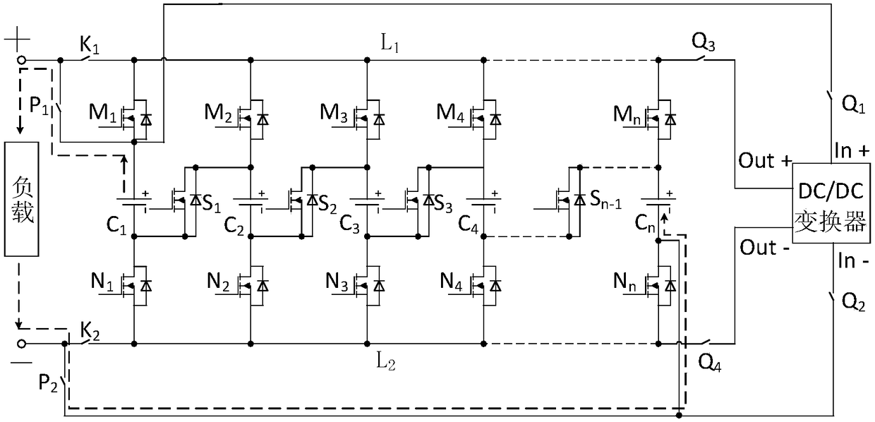
[0030] During charging (such as Figure 4 , 5 ), assuming that the order in which the cells reach the charge cut-off voltage is C 3 、C 1 、C 2 、C 4 、C5 , the specific circuit control method is as follows: turn on the bus switch (K 1 、K 2 ) At this time, because it is in the charging state (that is, the external power supply charges the battery pack), the current goes through the charging circuit, so the control bus switch (P 1 ,P 2 ) is disconnected. No additional balancing circuit is needed during the charging process, so the control switch (Q 1 , Q 2 , Q 3 , Q 4 ) is in the disconnected state, completely isolating the DC / DC converter out of the circuit. During the whole charging process, the single battery C 1 、C 2 、C 3 、C 4 、C 5 are in parallel state, (1), when the single battery C 3 When the set charging cut-off voltage is reached, the control and the single battery C 3 Two Mosfet switches in seri...


PUM


Abstract

The invention relates to an equalization circuit realizing parallel charging and selective single cell battery equalization discharge and a control method thereof. The equalization circuit is composedof a battery pack, a DC/DC converter, Mosfet switches with anti-parallel diodes, a bus switch K1, a bus switch K2, a bus switch P1, a bus switch P2, a switch Q1, a switch Q2, a switch Q3 and a switchQ4. The equalization circuit can realize parallel charging, when any single cell battery reaches the set cutoff voltage, the single cell battery is isolated from a charging circuit, finally all single cell batteries are stopped charging when reach the set charging cutoff voltage, and the forced balance purpose is achieved. According to the equalization discharge, the battery pack is connected tothe DC/DC converter in parallel to perform equalization on the single cell battery with the lowest state of charge (SOC) in the battery pack. During discharging, the inconsistency between all the single cell batteries can be effectively reduced.

Description

technical field [0001] The invention relates to an equalization circuit for parallel charging and selective single cell discharge equalization and a control method thereof, belonging to the technical fields of power electronics technology and storage battery group energy balance management. Background technique [0002] With the development of the times, the advancement of science and technology, environmental problems and energy crises are becoming more and more serious, especially the excessive exploitation and use of fossil fuels such as oil and coal, which has caused the greenhouse effect to intensify, and these primary energy sources are non-renewable and are also facing depletion. question. The sustainable development of mankind is facing enormous challenges. In today's era of rapid economic development, automobiles have become the main means of transportation, while accelerating the consumption of fossil energy and exacerbating the deterioration of the environment. ...

Claims


Application Information

Patent Timeline
Patent Type & Authority Applications(China)
IPC IPC(8): B60L11/18
CPCB60L53/60B60L58/10B60L58/18B60L58/22B60L2210/10Y02T10/72Y02T10/70Y02T90/12Y02T10/7072
Inventor 刘红锐李博杜春峰陈仕龙
Owner KUNMING UNIV OF SCI & TECH
Why Eureka
Try Eureka