
Blade beam cap laying trolley
A technology of trolleys and blades, which is applied in the direction of spreading thin soft materials, winding strips, thin material processing, etc. It can solve the problems of poor tension control of prepreg rolls, affecting the quality of spreading, and wrinkles in the cloth layer. Achieve the effect of eliminating internal stress between cloth layers, improving spreading quality and spreading efficiency, and uniform tension
- Summary
- Abstract
- Description
- Claims
- Application Information
AI Technical Summary
Problems solved by technology
Method used
Image

Examples
Embodiment
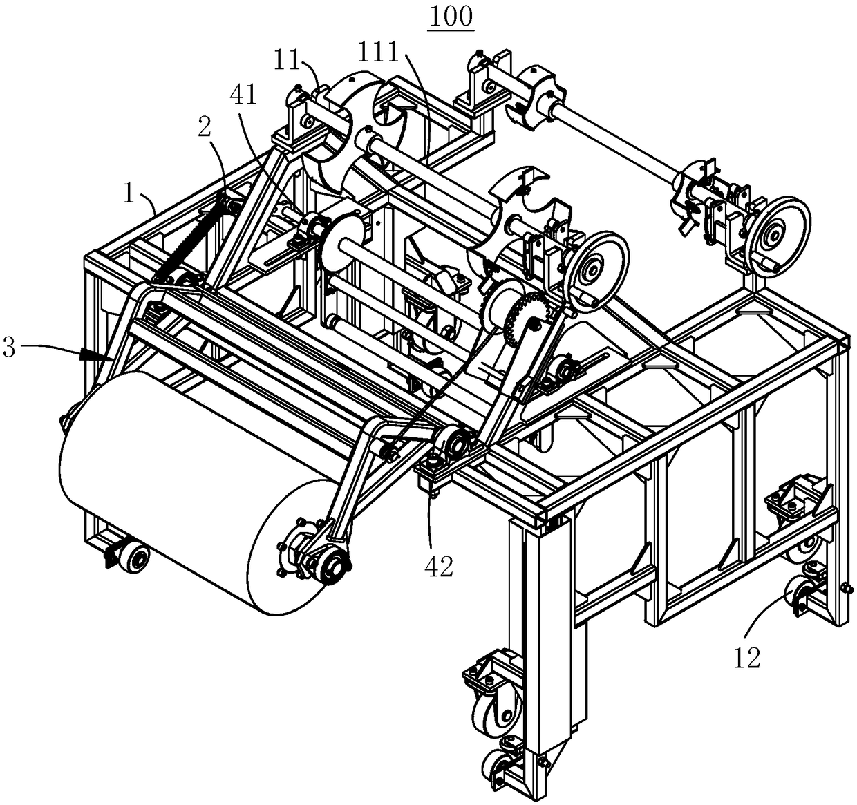
[0037] Please refer to figure 1 , the present embodiment provides a blade spar cap spreading trolley 100 , including a frame 1 , a tension adjusting mechanism 2 and a cloth laminating roller mechanism 3 .
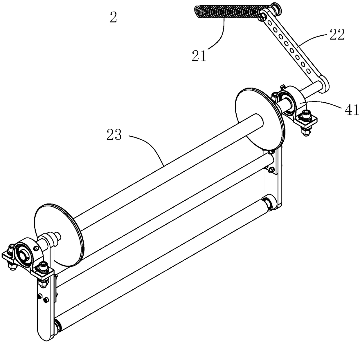
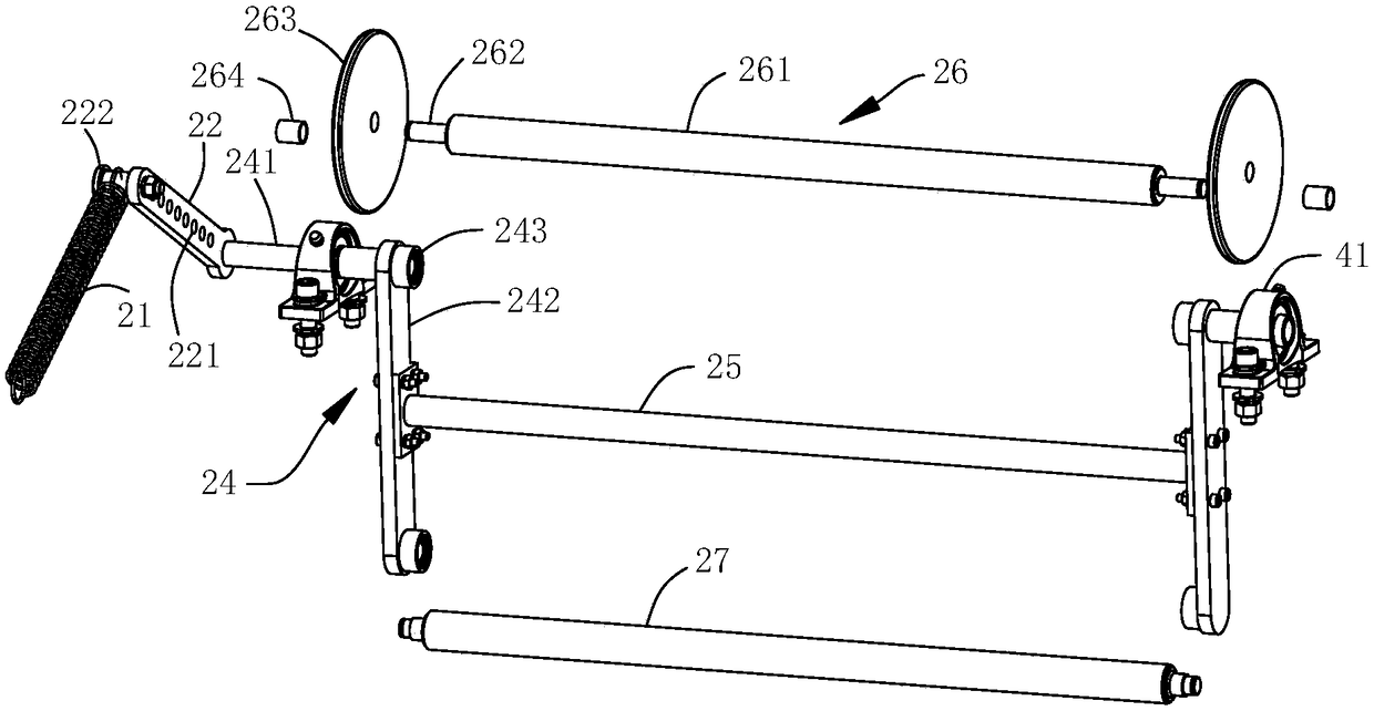
[0038] Such as Figure 1-Figure 7 As shown, in this embodiment, the tension adjustment mechanism 2 includes a tension spring 21, an adjustment swing arm 22 and a tension adjustment assembly 23. One end of the tension spring 21 is fixed to the vehicle frame 1, and the other end is connected to the adjustment swing arm 22. The arm 22 is connected in transmission with the tension adjustment assembly 23, the tension adjustment assembly 23 is rotatably connected with the vehicle frame 1 through the first bearing seat 41, the tension spring 21 exerts a pulling force on the adjustment swing arm 22, and the tension spring 21 can drive the tension adjustment assembly 23 rotates relative to the vehicle frame 1, thereby changing the tension of the cloth (cloth layer) passing through ...
PUM
 Abstract
Description
Claims
Application Information