
Hydraulic two-way splitting rod

A splitting rod and hydraulic technology, which is used in fluid pressure actuating devices, discharging machinery, earth-moving drilling, etc., can solve problems such as uneven force on splitting rods, scrapping of splitting rod equipment, and large vibration of transmission accuracy. , to achieve good splitting effect, improve splitting efficiency and improve efficiency

Inactive Publication Date: 2018-09-28
CHINA UNIV OF MINING & TECH
View PDF10 Cites 8 Cited by
  • Summary
  • Abstract
  • Description
  • Claims
  • Application Information

AI Technical Summary

Problems solved by technology

[0003] However, the splitting rods used on this common splitting machine have the following technical defects during use: because the holes drilled on the rock are not all regular round holes or square holes, due to site conditions, construction techniques, etc. As a result, the drilled hole is irregular, and the splitting rod will be subject to a large reaction force during the process of splitting the rock. If the shape of the drilled hole is very irregular, it will make the splitting rod everywhere Due to uneven force, cracks or overall fractures will eventually lead to the scrapping of the entire set of splitting rod equipment
[0005] The following problems exist in this kind of mechanically driven bidirectional splitting rod: due to the high machining precision of the screw drive and the large difference in working speed, the wear is large, the life is short, and it is prone to crawling after a period of use; the precision of processing, installation and adjustment High, which increases the cost of equipment; due to the mechanical transmission during use, once the transmission accuracy changes due to wear and tear, it will cause problems such as excessive vibration and loud noise; and this structure has no overload protection, and it is easy to damage and fail

Method used


Image

  • Hydraulic two-way splitting rod
  • Hydraulic two-way splitting rod
  • Hydraulic two-way splitting rod

Examples


Embodiment Construction

[0023] The present invention will be described in detail below in conjunction with the accompanying drawings.

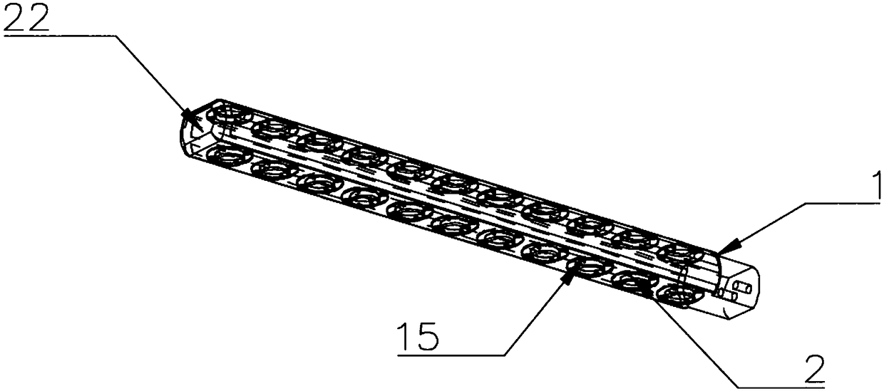
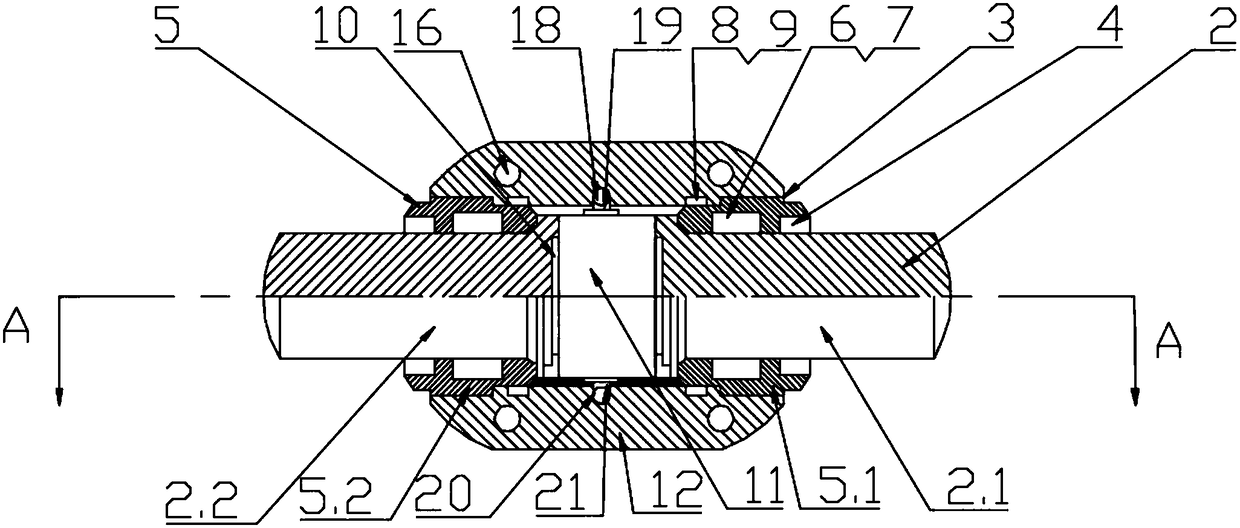
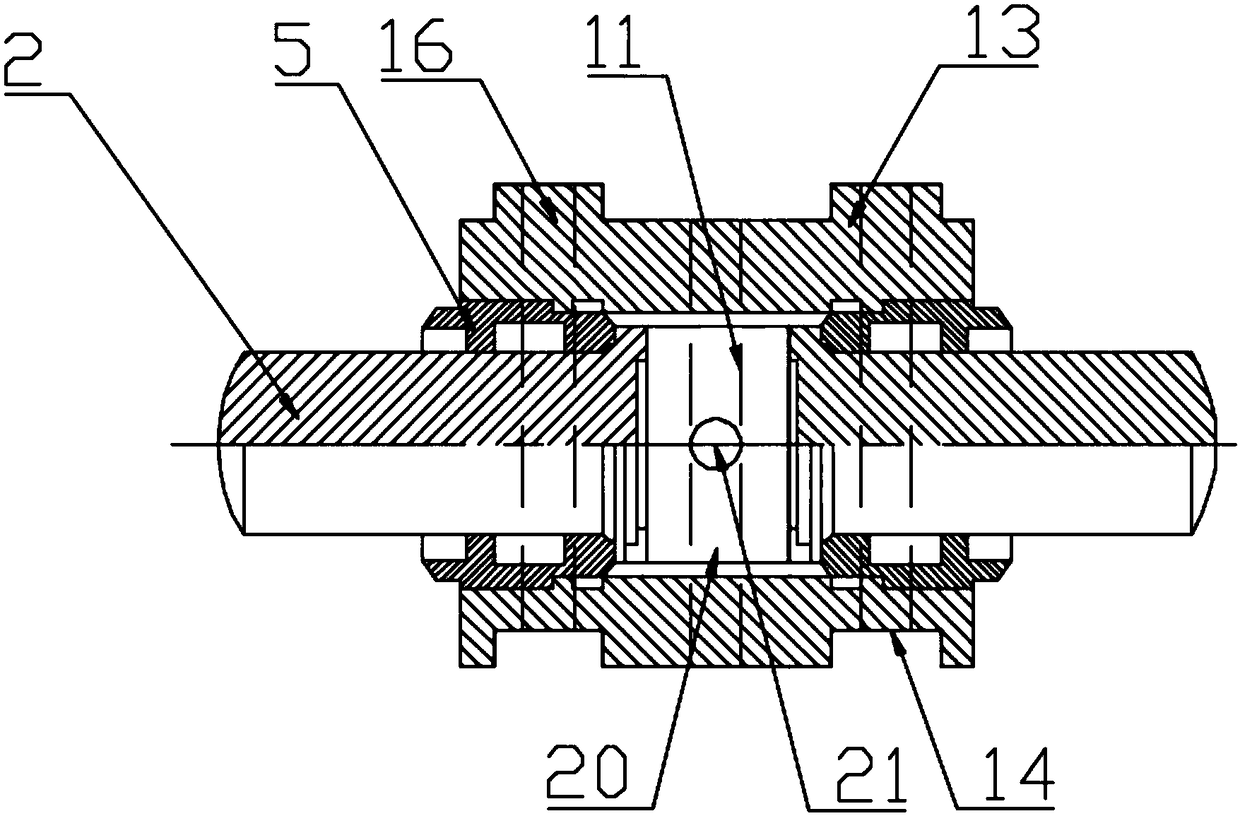
[0024] Such as Figure 1 to Figure 4 As shown, a hydraulic two-way splitting rod comprises a rod shell 1 and a hydraulic cylinder, and the rod shell 1 offers a plurality of through holes 15 that allow the piston rod of the hydraulic cylinder to stretch out; the hydraulic cylinder is a two-way hydraulic cylinder 3, and the rod Both sides of the shell 1 are provided with through holes 15, and a plurality of the above-mentioned two-way hydraulic cylinders 3 are longitudinally arranged in the rod shell 1. The hydraulic cylinder 3 shares the same oil inlet channel 18 and oil return channel 20; the two-way hydraulic cylinder 3 includes a cylinder body 12, a cylinder liner 5, a piston rod 2 and a seal, and the first piston rod 2.1 and the second piston rod 2.2 are symmetrically arranged, and the piston Rod one 2.1 is installed on one side of cylinder body 12 through cylind...


PUM


Abstract

The invention discloses a hydraulic two-way splitting rod. Multiple two-way hydraulic cylinders are longitudinally arranged in a rod shell; each two-way hydraulic cylinder is connected with the adjacent two-way hydraulic cylinders end to end; all the two-way hydraulic cylinders in the rod shell share the same oil inlet channel and the same oil return channel; the two-way hydraulic cylinders comprise cylinder blocks, cylinder jackets, piston rods and sealing pieces; piston cavities are formed between first piston rods and second piston rods; the oil inlet channel is arranged on one sides of thepiston cavities, and communicates with the piston cavities through oil inlet holes; and the oil return channel is arranged on the other sides of the piston cavities, and communicates with the pistoncavities through oil return holes. Compared with a traditional splitting rod, the splitting rod is uniformly stressed in non-uniform cylinder holes through two-way piston systems, so that the damage to the splitting rod by reactive force of rocks can be prevented, and the service life is prolonged; and the splitting rod is large in travel, improves the splitting efficiency, simple and compact in overall structure and convenient to install and maintain.

Description

technical field [0001] The invention relates to a rock splitting mechanism, in particular to a hydraulic two-way splitting rod. Background technique [0002] In traditional rock mining and mining, whether it is open-pit mining or underground mining, most of them use the method of drilling and blasting. With the development of my country's economy, environmental protection and construction personnel safety considerations, the control of blasting charges is becoming more and more strict. , so the mechanical crushing method has been more and more widely used. Among them, the most common mechanical crushing method is the splitter, which is a high-efficiency crushing equipment that uses hydraulic mechanical methods to split rocks. It consists of two parts: a hydraulic power station and a splitting rod. The splitting rod The ultra-high pressure oil output from the pump station drives the cylinder to generate a huge driving force, and multiple plungers work together to split hard o...

Claims


Application Information

Patent Timeline
IPC IPC(8): F15B15/14F15B15/20E21C37/06
CPCF15B15/1404E21C37/06F15B15/1409F15B15/1428F15B15/20
Inventor 刘送永沈刚江红祥黄举胡正伟
Owner CHINA UNIV OF MINING & TECH
Learn More