Disc spring damper capable of adjusting damping and rigidity

A disc spring and damper technology, applied in the direction of spring/shock absorber, spring/shock absorber design features, spring/shock absorber functional characteristics, etc., can solve the problem that linear shock absorbers cannot take into account multiple technical indicators, High service life requirements, small change range, etc., to achieve the effects of adjustable damping and stiffness, weight reduction, and friction reduction

Inactive Publication Date: 2018-09-28
SHANGHAI RES INST OF MATERIALS CO LTD
View PDF7 Cites 10 Cited by
  • Summary
  • Abstract
  • Description
  • Claims
  • Application Information

AI Technical Summary

Problems solved by technology

However, the disadvantages of using the wire rope pretension device are: (1) the pretension force of the wire rope is generally 1% to 2% of its breaking force, and it can be seen that the range of change in the pre-stiffness of the disc spring assembly is very small; (2) when it is used When the vibration isolation object vibrates and presses the disc spring assembly, the disc spring moves downward due to elastic deformation, and the wire rope is in a relaxed state. Once the vibration isolation object is buffered upwards, the disc spring assembly actively resets, and the wire rope is suddenly in a tight state. The sudden change in the working state of the wire rope has high requirements on its service life, and there are also certain safety hazards
[0004] At the same time, in modern engineering practice, the requirements for the working frequency band, installation space and temperature and weather resistance of the vibration isolator are getting higher and higher. Conventional linear vibration absorbers often cannot take into account multiple technical indicators. This type of engineering practice Promote the development of nonlinear vibration reduction technology

Method used


Image

  • Disc spring damper capable of adjusting damping and rigidity

Examples


Embodiment

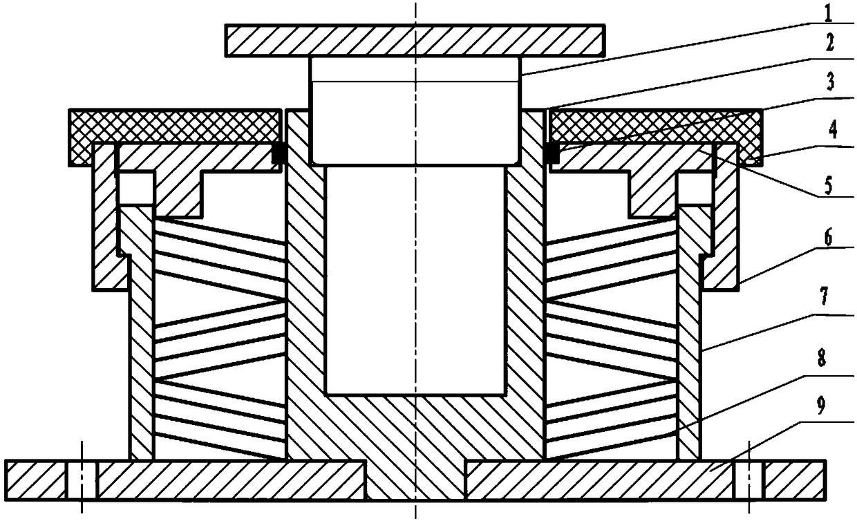
[0034] A disc spring damper with adjustable damping and stiffness, such as figure 1 , including a disc spring 8, a fixing screw 1, an inner guide shaft 2, a bearing 3, an upper cover plate 4, an end cover 5, a locking sleeve 6, a cylinder body 7 and a base 9, and the cylinder body 7 is fixed on the base 9, The inner guide shaft 2 is located in the cylinder body 7, the inner guide shaft 2 is connected on the base 9, the fixing screw 1 is connected in the inner guide shaft 2, the end cover 5 is arranged on the upper end of the cylinder body 7, and the connection between the end cover 5 and the inner guide shaft 2 The bearing 3 is fixed between them, the locking sleeve 6 is connected to the outside of the cylinder body 7, the upper cover plate 4 is set on the upper end of the end cover 5 and the locking sleeve 6, and the disc spring 8 is arranged on the inner guide shaft 2 and the cylinder body 7. Between them, the upper and lower ends of the disc spring 8 are in contact with the...


PUM


Abstract

The invention relates to a disc spring damper capable of adjusting damping and rigidity. The disc spring damper capable of adjusting damping and rigidity comprises a disc spring, a fixed screw, an inner guide shaft, a bearing, an upper cover plate, an end cover, a locking sleeve, a cylinder block and a base; the cylinder block is fixed on the base; the inner guide shaft is positioned in the cylinder block; the inner guide shaft is connected to the base; the fixed screw is connected into the inner guide shaft; the end cover is arranged at the upper end of the cylinder block; the bearing is fixed between the end cover and the inner guide shaft; the locking sleeve is connected to the outer side of the cylinder block; the upper cover plate is arranged at the upper ends of the end cover and thelocking sleeve; the disc spring is arranged between the inner guide shaft and the cylinder block; the upper and lower ends of the disc spring butt against the end cover and the base; the upper coverplate is used for bearing damped objects; the fixed screw is used for realizing limiting of the damped objects; and the base is used for connecting with a foundation. The disc spring damper capable ofadjusting damping and rigidity has the advantages of damping and rigidity adjustability, high energy consumption capacity, stable performances, convenience to operate, low cost and the like.

Description

technical field [0001] The invention belongs to the technical field of vibration reduction and isolation, in particular to a disc spring damper with adjustable damping and stiffness. Background technique [0002] Vibration widely exists in engineering technology and daily life, and this ubiquitous phenomenon is attracting increasing attention. In engineering, people use the advantages of vibration to develop vibration equipment, such as vibration conveying, vibration screening, vibration grinding, etc., which greatly improve working conditions and increase productivity. However, vibration also has a negative side, which not only affects the service life of machinery and equipment, the performance of instruments and equipment, and the stability of building structures, but also the noise generated by vibration also affects people's work, life and health. Effective isolation control of vibration is a top priority. How to ensure the normal operation of some high-tech, sophisti...

Claims


Application Information

Patent Timeline
Patent Type & Authority Applications(China)
IPC IPC(8): F16F13/00F16F9/30F16F3/02
CPCF16F13/00F16F3/023F16F9/306F16F2228/063F16F2230/0005F16F2238/022
Inventor 涂田刚朱唯丰张诗悦徐斌丁孙玮杨俊徐校春
Owner SHANGHAI RES INST OF MATERIALS CO LTD
Why Eureka
Try Eureka