Pressure follow-up temperature control system special for wind power cooler

A temperature control system and cooler technology, applied in wind turbines, wind energy power generation, machines/engines, etc., can solve the problems of large damage rate of temperature bulb expansion temperature control valves, affecting equipment reliability, etc., achieving simple structure and reducing The effect of fan shutdown maintenance and failure resolution

Pending Publication Date: 2018-09-28
南京孚奥智能技术有限公司
View PDF7 Cites 1 Cited by
  • Summary
  • Abstract
  • Description
  • Claims
  • Application Information

AI Technical Summary

Problems solved by technology

[0002] The lubricating oil flow of the filter device of the wind power lubrication system is controlled by the temperature bulb expansion temperature control valve. When the temperature is lower than 45°C, the lubricating oil goes directly to the distributor without passing through the cooler; when the temperature rises to 45°C, the valve core Start to move, and gradually close the branch to the distributor. When the temperature rises to 60°C, the branch to the distributor is fully closed; due to the frequent action of the temperature control valve at low temperature, the damage rate of the temperature bulb expansion temperature control valve is too high, which is serious Affect the reliability of the equipment

Method used


Image

  • Pressure follow-up temperature control system special for wind power cooler
  • Pressure follow-up temperature control system special for wind power cooler
  • Pressure follow-up temperature control system special for wind power cooler

Examples


Embodiment Construction

[0018] The specific implementation manners of the present invention will be further described in detail below in conjunction with the accompanying drawings and embodiments. The following examples are used to illustrate the present invention, but are not intended to limit the scope of the present invention.

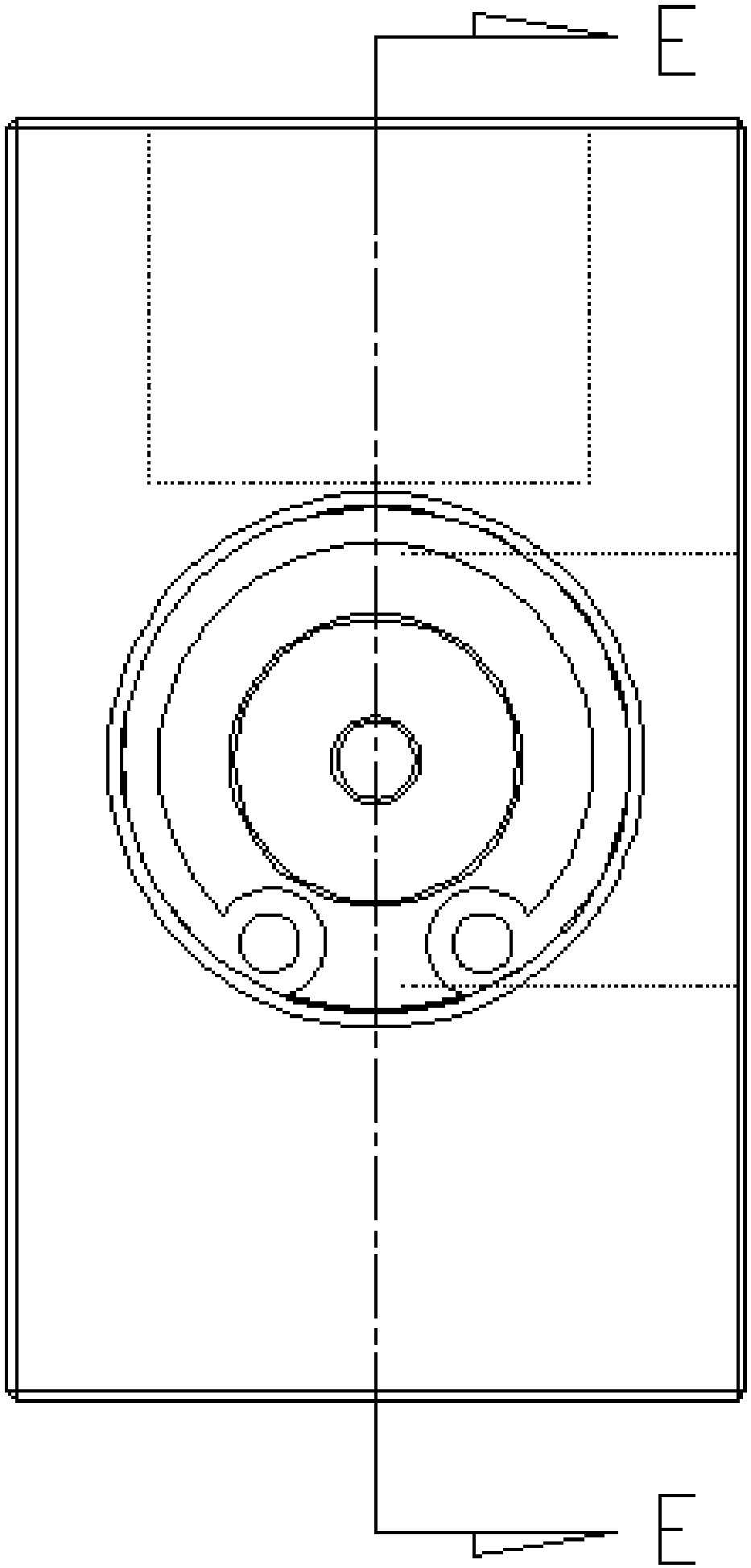
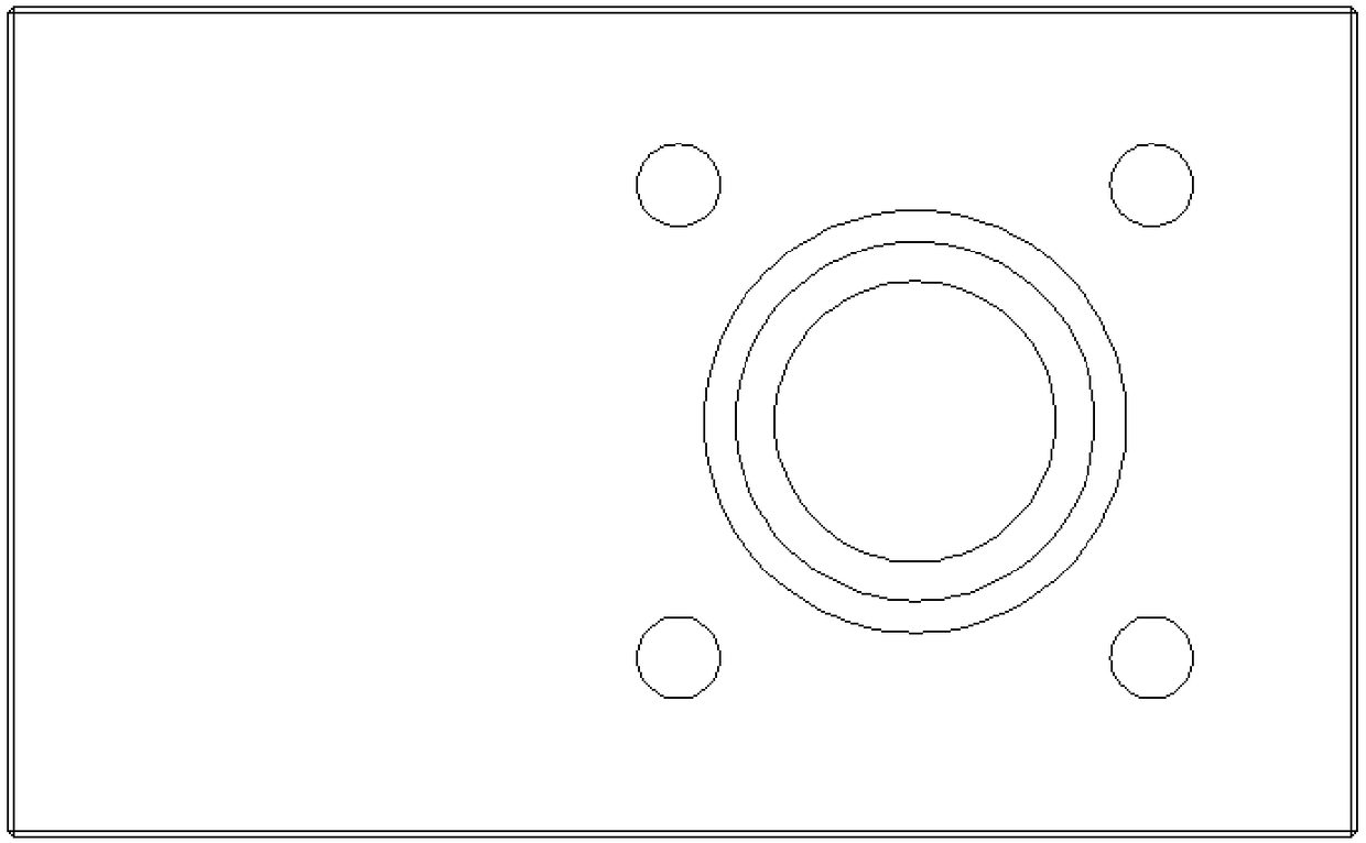
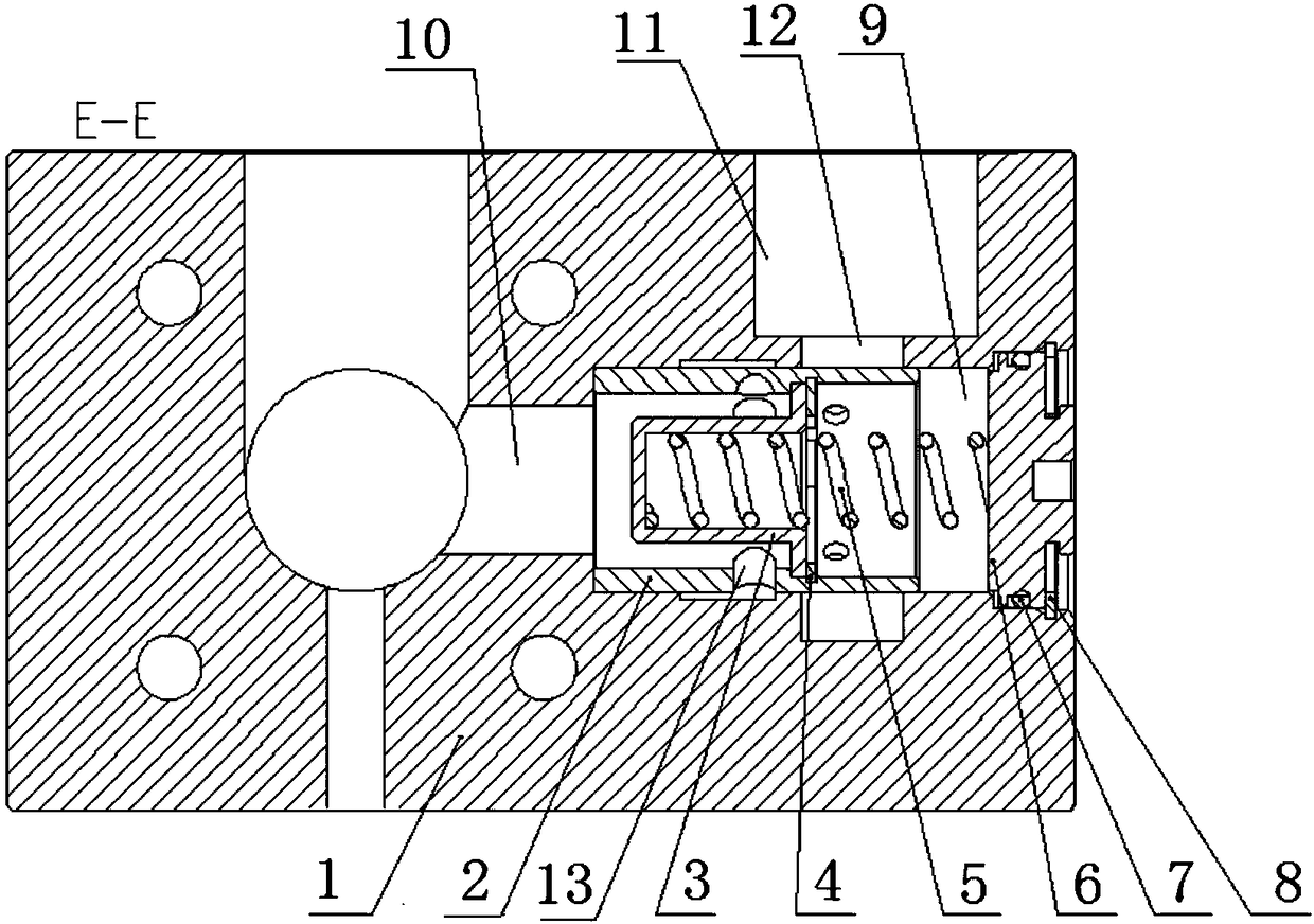
[0019] Such as Figure 1~3 As shown, a special pressure-following temperature control system for wind power coolers, including a pressure-following temperature control valve, the pressure-following temperature control valve includes a valve body 1, a sliding chamber 9 is arranged in the valve body 1, and the sliding chamber 9 is A valve core 2 capable of reciprocating sliding along the sliding chamber 9 is provided. The valve core 2 is a hollow cylinder whose outer wall fits the inner wall of the sliding chamber 9. The valve body 1 is provided with an inlet 10 and an outlet 11. The circumferential direction of the sliding chamber 9 There is an annular groove 12, the annul...


PUM


Abstract

The invention discloses a pressure follow-up temperature control system special for a wind power cooler. The pressure follow-up temperature control system comprises a pressure follow-up temperature control valve; the pressure follow-up temperature control valve comprises a valve body, a sliding cavity is formed in the valve body, a valve element capable of sliding along the sliding cavity in a reciprocating mode is arranged in the sliding cavity, the valve element is a hollow cylinder which is attached to the inner wall of the sliding cavity through the outer wall, an inlet and an outlet are formed in the valve body, an annular groove is formed in the circumferential direction of the sliding cavity, the annular groove communicates with the outlet, one end of the sliding cavity communicateswith the inlet, the other end of the sliding cavity is provided with a blocking piece, a valve cap is arranged in the valve element, the cap edge of the valve cap is connected with the inner wall ofthe valve element, the two ends of the spring abut against the valve cap and the blocking piece respectively, an overflowing hole is formed in the side wall of the valve element, and the overflow holecommunicates with an inlet through a cavity between the valve element and the valve cap. According to the pressure follow-up temperature control system, the pressure difference of the lubricating oilat different temperatures is controlled to be switched on and off, so that a switch function can be realized, an existing temperature control valve can be replaced, the problem that the fault rate ofthe temperature control valve is high is solved, and shutdown and maintenance of a fan are reduced.

Description

technical field [0001] The invention relates to the technical field of a wind power lubricating oil switch, in particular to a special pressure-following temperature control system for a wind power cooler. It is suitable for wind power lubrication systems with coolers installed. The pressure difference generated when the temperature of the lubricating oil changes can control the flow of the lubricating oil entering the cooler and the lubricating oil bypassing the cooler, so as to realize the control of the cooling back end lubricating oil temperature. Background technique [0002] The lubricating oil flow of the filter device of the wind power lubrication system is controlled by the temperature bulb expansion temperature control valve. When the temperature is lower than 45°C, the lubricating oil goes directly to the distributor without passing through the cooler; when the temperature rises to 45°C, the valve core Start to move, and gradually close the branch to the distribu...

Claims


Application Information

Patent Timeline
Patent Type & Authority Applications(China)
IPC IPC(8): F16N23/00
CPCF03D80/70F16N23/00F16N2270/56Y02E10/72
Inventor 艾文峰
Owner 南京孚奥智能技术有限公司
Why Eureka
Try Eureka