Optical system
An optical system and optical film technology, which is applied in the field of optical systems, can solve problems such as difficulty in ensuring imaging consistency, information leakage, and complicated processes, and achieve the effects of wide human eye movement range, avoiding information leakage, and good imaging quality
- Summary
- Abstract
- Description
- Claims
- Application Information
AI Technical Summary
Problems solved by technology
Method used
Image

Examples
Embodiment approach 1
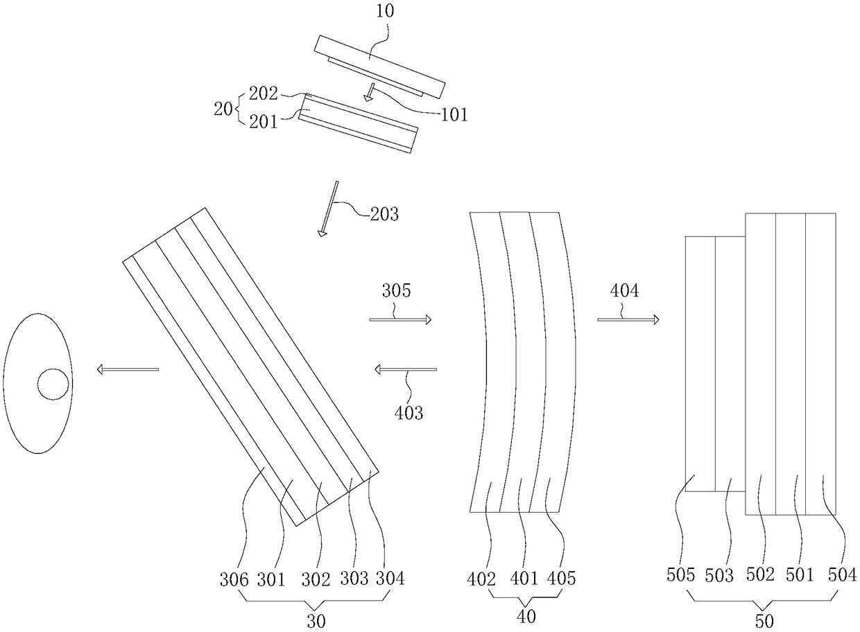
[0032] refer to figure 1 As shown, Embodiment 1 of the present invention provides an optical system, which is mainly applied to head-mounted products, such as AR glasses. The optical system includes a display system 10, a first optical lens 20, a second optical lens 30, The third optical lens 40 and the fourth optical lens 50 .
[0033] The display system 10 mainly plays the role of emitting light, and the light emitted by the display system 10 is defined as incident light 101 . In this embodiment, the display system 10 is an OLED display system or an LED display system, and the light emitted by the display system 10 is non-polarized light. Of course, the display system 10 can also adopt other display systems 10 that meet the requirements.
[0034] The first optical lens 20 is arranged on the optical path of the incident light 101, and the function of the first optical lens 20 is to reduce field curvature, distortion and dispersion. The quantity of the first optical lens 20...
Embodiment approach 2
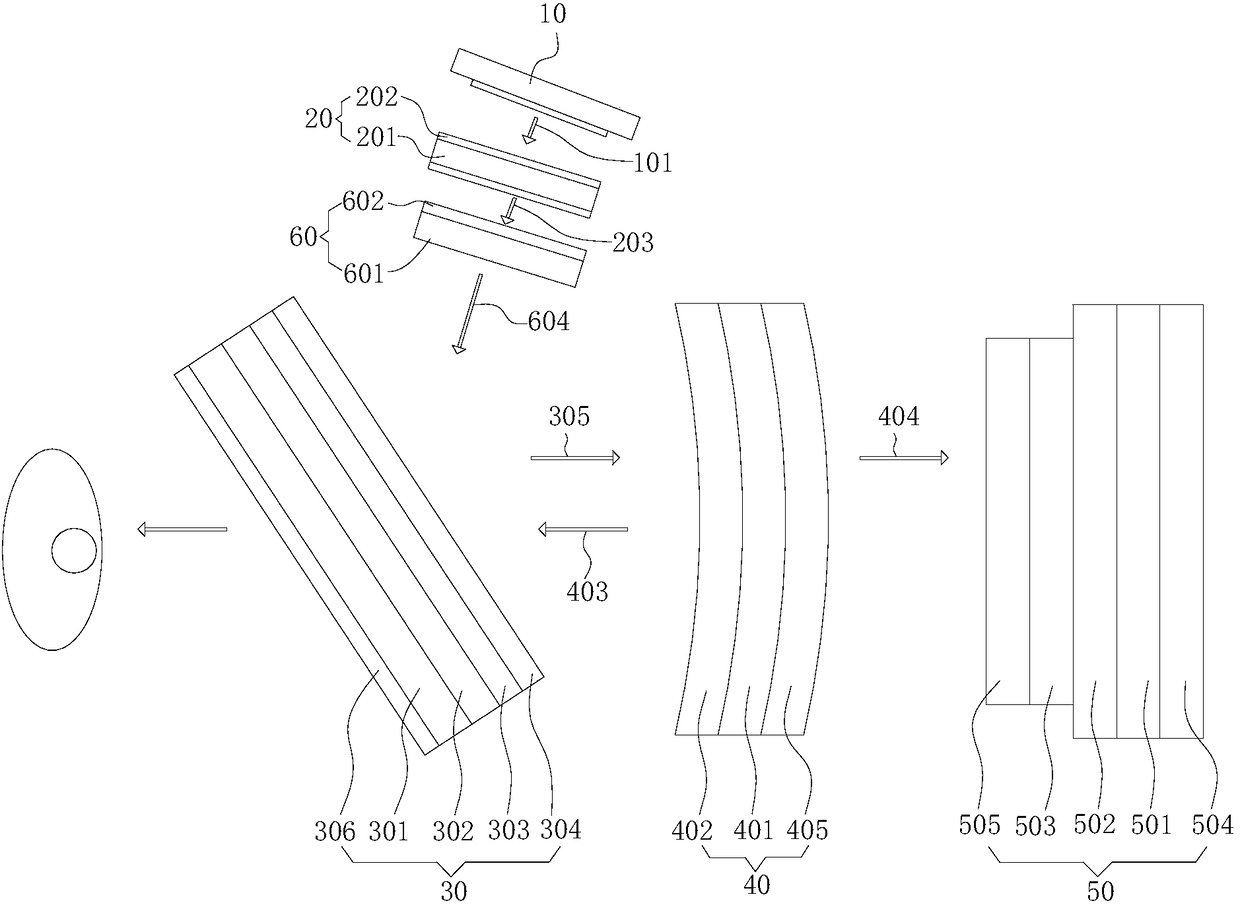
[0052] refer to figure 2 As shown, Embodiment 2 of the present invention provides an optical system, which is mainly applied to head-mounted products, such as AR glasses. The optical system includes a display system 10, a first optical lens 20, a second optical lens 30, The third optical lens 40 , the fourth optical lens 50 and the fifth optical lens 60 .
[0053] It should be noted that the first optical lens 20, the second optical lens 30, the third optical lens 40 and the fourth optical lens 50 in this embodiment adopt the first optical lens 20 and the second optical lens 30 in the first embodiment. 1. For the structure, working principle and technical effects of the third optical lens 40 and the fourth optical lens 50 , reference may be made to the corresponding content in Embodiment 1, which will not be repeated here.
[0054] The display system 10 in this embodiment adopts an LCOS display system, and may also adopt an LCD display system. The light emitted by the LCOS ...
Embodiment approach 3
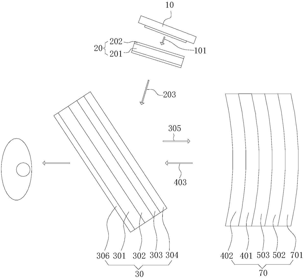
[0061] refer to image 3 As shown, Embodiment 3 of the present invention provides an optical system, which is mainly applied to head-mounted products, such as AR glasses. The optical system includes a display system 10, a first optical lens 20, a second optical lens 30 and The sixth optical lens 70 .
[0062] It should be noted that the display system 10, the first optical lens 20 and the second optical lens 30 in this embodiment adopt the display system 10, the first optical lens 20 and the second optical lens 30 in Embodiment 1, and its structure, For the working principle and the generated technical effects, reference may be made to the corresponding content in Embodiment 1, and details are not repeated here.
[0063] The sixth optical lens 70 is disposed on the optical path of the first reflected light 305 .
[0064] The sixth optical lens 70 includes a linear polarizer 502, a second quarter-wave plate 503, a second optical plate 401 and a third optical film 402 that are...
PUM
 Abstract
Description
Claims
Application Information
 - R&D
- Intellectual Property
- Life Sciences
- Materials
- Tech Scout
- Unparalleled Data Quality
- Higher Quality Content
- 60% Fewer Hallucinations
Browse by: Latest US Patents, China's latest patents, Technical Efficacy Thesaurus, Application Domain, Technology Topic, Popular Technical Reports.
© 2025 PatSnap. All rights reserved.Legal|Privacy policy|Modern Slavery Act Transparency Statement|Sitemap|About US| Contact US: help@patsnap.com