An electric bus charging joint device

A technology of charging joints and electric buses, which is applied in the direction of electric vehicle charging technology, electric vehicles, parts of connecting devices, etc., can solve problems that are contrary to vehicle weight reduction, energy saving and emission reduction, damage, and increase of vehicle load.

Inactive Publication Date: 2020-10-30
ZHEJIANG UNIV
View PDF5 Cites 0 Cited by
  • Summary
  • Abstract
  • Description
  • Claims
  • Application Information

AI Technical Summary

Problems solved by technology

[0002] With the continuous development of new energy technology, a large number of new energy buses have been put into operation in various cities. However, electric buses have the following disadvantages: First, the cost of electric buses is relatively high, the main reason is that electric buses The price of the battery of the car is relatively high; secondly, the capacity of the existing battery is small, so that the battery life of the car is not high. Generally, the method of adding battery packs is used to improve the battery life, but this method will increase the load of the car, and there are Contrary to the goals of lightweight vehicles and energy saving and emission reduction; third, the charging facilities for electric buses are not perfect, the number of existing charging piles is limited, and the charging efficiency is relatively low, which is not conducive to the use and distribution of a large number of electric buses
[0003] Most of the existing bus charging connectors are located on the side of the bus. When the charging connector is located on the roof of the bus platform, the charging connector needs to be installed on the top of the bus. If it is exposed to the air, it is easily damaged by harsh natural environments such as rain and snow.
At the same time, when the bus charging connector is located on the top of the bus, it is difficult to realize the docking of the manual operation of the bus charging connector and the charging interface on the bus platform

Method used


Image

  • An electric bus charging joint device
  • An electric bus charging joint device
  • An electric bus charging joint device

Examples


Embodiment 1

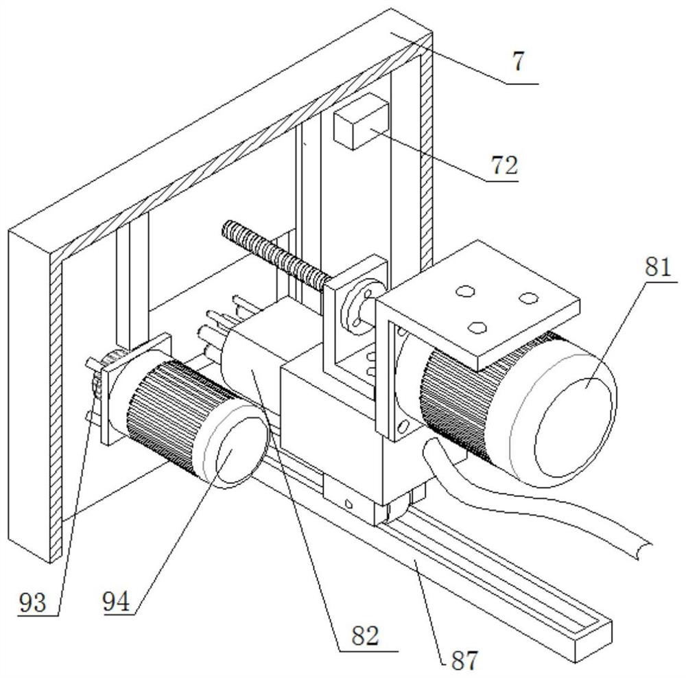
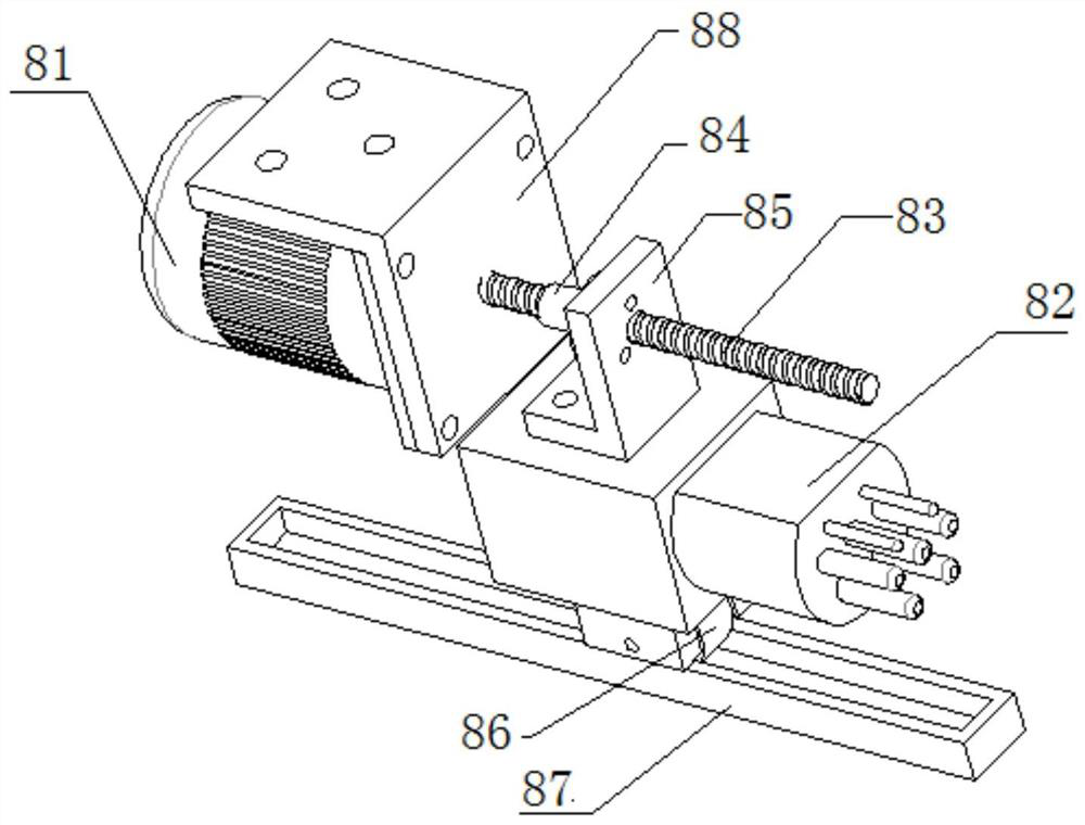
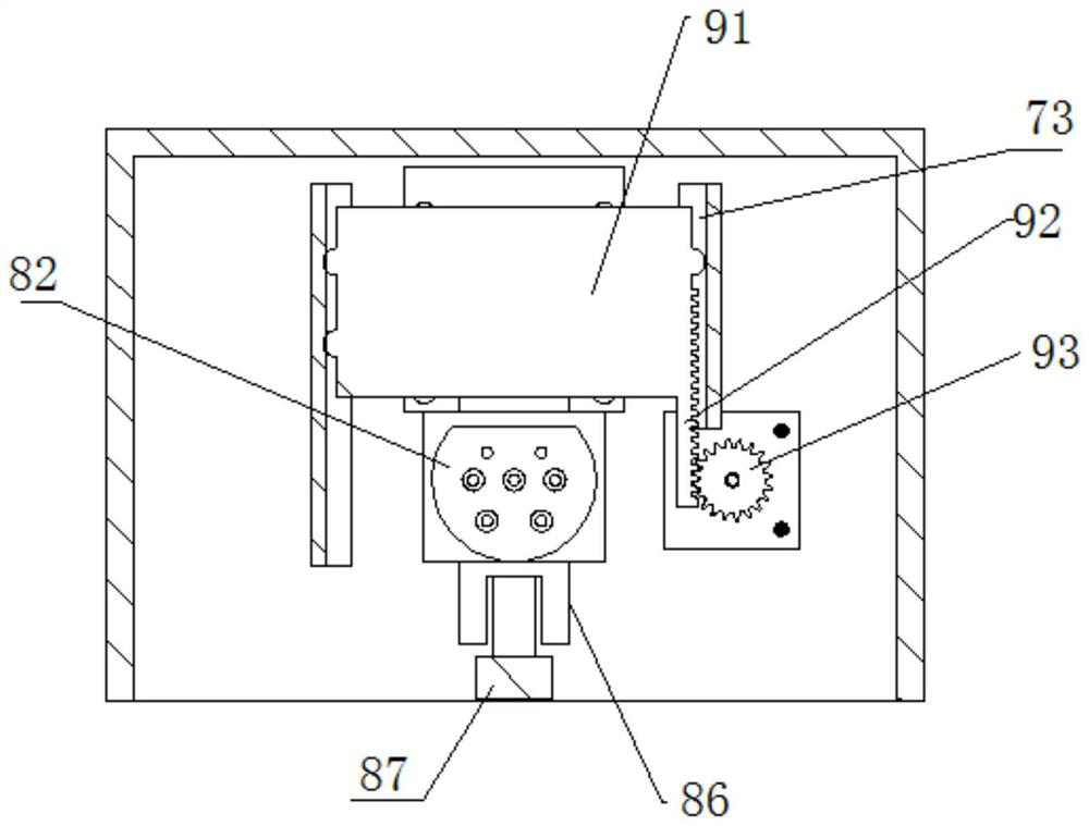
[0043] An electric bus charging connector device, such as Figure 1-5 As shown, it includes a charging connector box 7, a charging connector moving mechanism 8 and a flap lifting mechanism 9; the charging connector box 7 has an opening 71 for the charging connector to enter and exit; the charging connector moving mechanism 8 and the flap lifting mechanism 9 are both located at the charging connector Inside the box 7, the charging connector moving mechanism 8 includes a charging connector driving motor 81 that provides driving force. The charging connector driving motor 81 is fixed to the box body through a first connecting member 88, the charging connector 82, the lead screw 83 and the lead screw nut 84, The charging connector drive motor 81 is coaxial with the lead screw rod 83. The lead screw rod 83 engages with the lead screw nut 84 for transmission. The lead screw nut 84 is connected to the charging connector 82 through a connecting piece 85. A guide pulley 86 is provided und...

Embodiment 2

[0048] An automatic charging device for electric buses, such as Figure 6-9 As shown, the device is located above the bus station and includes a controller 1, an adjustment mechanism 2 and a positioning mechanism 3 arranged above the station; the adjustment mechanism includes a first arm 21, a second arm 22 and a charging interface 23, and the first arm 21 is fixed On the turntable 4, the turntable 4 rotates around the turntable shaft 41, the first arm servo motor 211 controls the movement of the first arm 21, the second arm servo motor 221 is fixed to the first arm 21, and the second arm servo motor 221 controls the movement of the second arm 22 , The second arm 22 is fixed to the interface servo motor 231, the interface servo motor 231 is connected to the connecting piece 233, the charging interface 23 is connected to the interface rotating motor 232, the interface rotating motor 232 is fixed to the connecting piece 233; the charging interface 23 is provided with a positioning ...

Embodiment 3

[0062] The difference between this embodiment and Embodiment 2 is that multiple charging ports are provided, and multiple charging ports are connected in series. Such as Figure 13-15 As shown, the charging interface 23 is provided with a first charging interface 234, a second charging interface 235 and a third charging interface 236, the first charging interface 234, the second charging interface 235 and the third charging interface 236 are connected in series in sequence.

[0063] The upper end of the second charging port 235 is provided with a vertical ultrasonic probe 313, the first charging port 234 is provided with a first horizontal ultrasonic probe 311, and the third charging port 236 is provided with a second horizontal ultrasonic probe 312, which is stepped vertically. The motor 333 drives the vertical ultrasonic probe 313 to rotate, the first horizontal stepping motor 331 drives the first horizontal ultrasonic probe 311 to rotate, and the second horizontal stepping moto...


PUM


Abstract

The invention discloses an electric bus charging connector apparatus. The electric bus charging connector apparatus comprises a charging connector box, a charging connector moving mechanism and a baffle lifting mechanism; an opening for allowing a charging connector to come in and go out is formed in one surface of the charging connector box; the charging connector moving mechanism and the bafflelifting mechanism are both positioned in the charging connector box; the charging connector moving mechanism comprises a charging connector driving motor for providing driving force, the charging connector, a lead screw threaded rod and a lead screw nut; the charging connector driving motor is coaxial with the lead screw threaded rod; the lead screw threaded rod and the lead screw nut are in meshed transmission; the lead screw nut is connected with the charging connector through a connecting piece; a guiding rail pulley is arranged below the charging connector, and the guiding rail pulley slides in a guiding rail; the baffle lifting mechanism comprises a baffle used for closing the opening; a rack is arranged on one side of the baffle; the rack and a gear arranged on the box are in meshedtransmission; and a baffle driving motor fixed with the inner wall of the box drives the gear to turn synchronously. The electric bus charging connector apparatus has effective waterproof and dustproof properties and can realize automatic butt jointing of the charging connector and a charging interface.

Description

Technical field [0001] The present invention relates to the field of charging joints, and more specifically, it relates to a charging joint device for electric buses. Background technique [0002] With the continuous development of new energy technology, a large number of new energy buses have been put into operation in various cities. However, electric buses have the following shortcomings: First, the cost of electric buses is relatively high, and the main reason is electric The price of car batteries is relatively high; second, the capacity of existing batteries is small, so the car’s endurance is not high. Generally, the method of adding battery packs is used to improve the endurance, but this method will increase the load of the car. Contrary to the goals of lightweight vehicles and energy saving and emission reduction; thirdly, the charging facilities of electric buses are not perfect, the number of existing charging piles is limited, and the charging efficiency is relativel...

Claims


Application Information

Patent Timeline
Patent Type & Authority Patents(China)
IPC IPC(8): H01R13/52H01R13/60H01R13/631H01R13/66H01R13/70B60L53/16
CPCB60L53/16H01R13/52H01R13/5213H01R13/60H01R13/631H01R13/66H01R13/6691H01R13/70H01R2201/26Y02T10/70Y02T10/7072Y02T90/14
Inventor 魏燕定王彦哲方升
Owner ZHEJIANG UNIV
Why Eureka
Try Eureka