High power density laser sputtering ionization time-of-flight mass spectrometer and use thereof

A technology of time-of-flight mass spectrometry and high power density, applied in the field of mass spectrometers, can solve the problems that mass spectrometers cannot meet the adaptability requirements, reduce the resolving power of the instrument, and cannot effectively separate ions, etc. Less destructive, character-changing effects

Inactive Publication Date: 2009-06-24
XIAMEN UNIV
View PDF0 Cites 16 Cited by
  • Summary
  • Abstract
  • Description
  • Claims
  • Application Information

AI Technical Summary

Problems solved by technology

However, when the traditional laser ionization mass spectrometer works, laser ionization is carried out in a high vacuum environment, and the ions generated by laser ionization will have an energy dispersion of up to thousands of electron volts, and a small amount of low ionization energy elements will be excessively ionized to produce divalent or multivalent ions, causing severe interference in the interpretation of spectra
In addition, the ions produced by ionization are introduced into the mass analyzer without cooling, which will make the ions with different mass-to-charge ratios unable to be effectively separated, reduce the resolution of the instrument, and cause the conventional mass spectrometer to fail to meet the adaptability requirements, resulting in traditional The applicability of laser ionization mass spectrometer is not good
These problems have not been resolved for a long time

Method used


Image

  • High power density laser sputtering ionization time-of-flight mass spectrometer and use thereof

Examples


Embodiment Construction

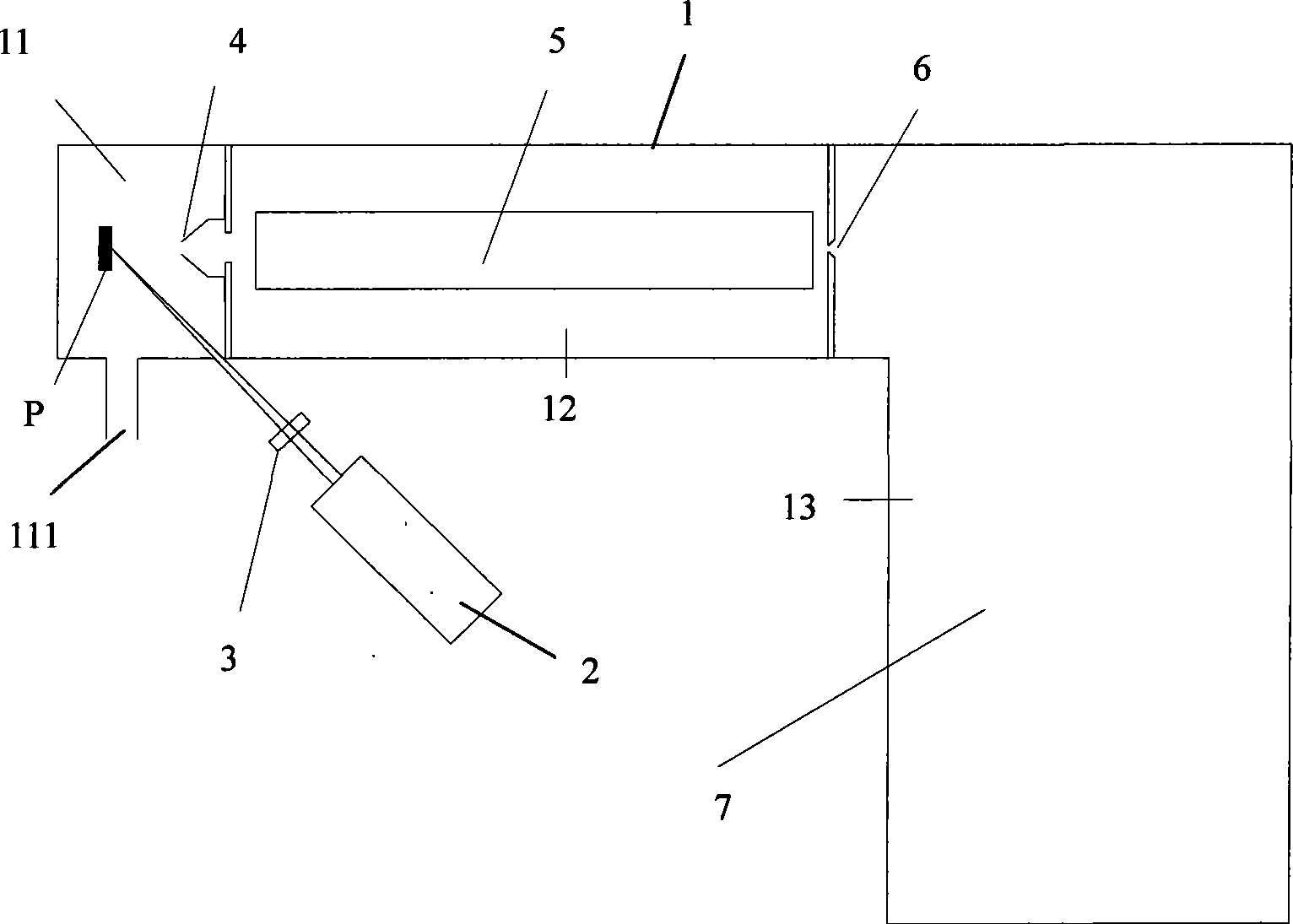
[0019] Such as figure 1 As shown, the present invention is provided with a vacuum cavity 1 , a laser 2 , a laser focusing lens 3 , a sampling cone 4 , an ion lens 5 (ie, an ion transmission device), a skimmer cone 6 and a time-of-flight mass analyzer 7 . The laser 2 and the laser focusing lens 3 are arranged outside the vacuum chamber 1 , and the sample P, the sampling cone 4 , the ion lens 5 , the skimmer cone 6 and the time-of-flight mass analyzer 7 are arranged in the vacuum chamber 1 in sequence.

[0020] The vacuum cavity 1 is provided with a three-stage vacuum chamber, the first-stage vacuum chamber 11 is before the sampling cone 4, the second-stage vacuum chamber 12 is between the sampling cone 4 and the skimmer cone 6, and the third-stage vacuum chamber 13 is behind the skimmer cone 6. The super-vacuum chamber 11 is provided with an auxiliary gas inlet 111 through which inert gases such as helium and argon are filled. The vacuum degree of the primary vacuum chamber 11...


PUM

PropertyMeasurementUnit
wavelengthaaaaaaaaaa
diameteraaaaaaaaaa
diameteraaaaaaaaaa

Abstract

A high-power density laser sputtering ionization flying time mass spectrometer and the application thereof relate to a mass spectrometer. A high-power density laser sputtering ionization flying time mass spectrometer and the application thereof are provided. The high-power density laser sputtering ionization flying time mass spectrometer is provided with a vacuum chamber, a laser source, a laser-focusing lens, a sampling cone, an ion transmission device, an interception cone and a flying time mass analyzer; the laser source and the laser-focusing lens are arranged outside the vacuum chamber; besides, the sampling cone, the ion transmission device, the interception cone and the flying time mass analyzer are sequentially arranged in the vacuum chamber. The vacuum chamber is provided with a third-level vacuum chamber; a first-level vacuum chamber is arranged in front of the sampling cone; a second-level vacuum chamber is arranged between the sampling cone and the interception cone; and the third-level vacuum chamber is arranged behind the interception cone. Through the collision with the auxiliary gas molecules (atoms) in the ion source, the kinetic energy of the sample irons is reduced to facilitate sampling and transmission; the multivalent ions lose valences and are converted into polyvalent ions to remove the interference peak of multivalent ions, so that the spectrum is clear and easy to read and has strong distinguishing ability.

Description

technical field [0001] The invention relates to a mass spectrometer, in particular to a high power density laser sputtering ionization time-of-flight mass spectrometer for direct analysis of solids without standard samples and its application. Background technique [0002] The analysis of elements in solid samples plays an important role in the fields of metallurgy, geology, mining, environmental protection, national defense, and semiconductor industry. Solid samples are usually dissolved and digested with strong acid, and then detected by atomic spectroscopy or mass spectrometry. In recent years, direct analysis methods of solid samples have attracted more and more attention. Compared with solid dissolution analysis, direct analysis can save a lot of sample preparation time, especially in the case of solid samples that are difficult to dissolve or highly toxic. In addition, the direct analysis of solid samples can not only avoid the loss and pollution during the dissolutio...

Claims


Application Information

Patent Timeline
Patent Type & Authority Applications(China)
IPC IPC(8): H01J49/40G01N27/64
Inventor 杭纬
Owner XIAMEN UNIV
Why Eureka
Try Eureka