Grounding protection switch of transformer neutral point

A transformer neutral point and grounding protection technology, which is applied to emergency protection circuit devices, emergency protection circuit devices for limiting overcurrent/overvoltage, electrical components, etc. Large workload and other issues, to achieve the effect of reducing production costs, reducing interference, and reducing the scope of power outages

Pending Publication Date: 2018-09-28
CHANGYUAN ELECTRIC TECH
View PDF0 Cites 0 Cited by
  • Summary
  • Abstract
  • Description
  • Claims
  • Application Information

AI Technical Summary

Problems solved by technology

However, the currently used neutral point protection methods all have different defects: 1) For equipment that uses a separate gap protection, the gap between the horizontal rods used for discharge is exposed in the air, and is easily affected by factors such as humidity, pollution, electrical corrosion, or chemicals. The protection function is reduced or the effect is not good, the discharge dispersion is large, the power frequency freewheeling current is large, and the arc extinguishing ability is poor
2) The equipment protected by surge arresters alone cannot protect against power frequency overvoltage, and it needs to be protected under high power frequency overvoltage, and there is a risk of failure. In addition, regular power outages are required for preventive tests, and the maintenance workload is relatively large. and affect system reliability
3) The gap and the lightning arrester are used for protection, but during the operation of the power grid, affected by external or system factors, the system parameters are constantly changing, which increases the difficulty of matching the lightning arrester and the parallel gap
It increases the difficulty of design, and when the zero-sequence impedance of the transformer changes, the original reactor complete set may need to be replaced, which not only increases the workload, but also causes a waste of resources

Method used


Image

  • Grounding protection switch of transformer neutral point
  • Grounding protection switch of transformer neutral point
  • Grounding protection switch of transformer neutral point

Examples


Embodiment Construction

[0020] The idea, specific structure and technical effects of the present invention will be clearly and completely described below in conjunction with the embodiments and accompanying drawings, so as to fully understand the purpose, features and effects of the present invention. Apparently, the described embodiments are only some of the embodiments of the present invention, rather than all of them. Based on the embodiments of the present invention, other embodiments obtained by those skilled in the art without creative efforts belong to The protection scope of the present invention.

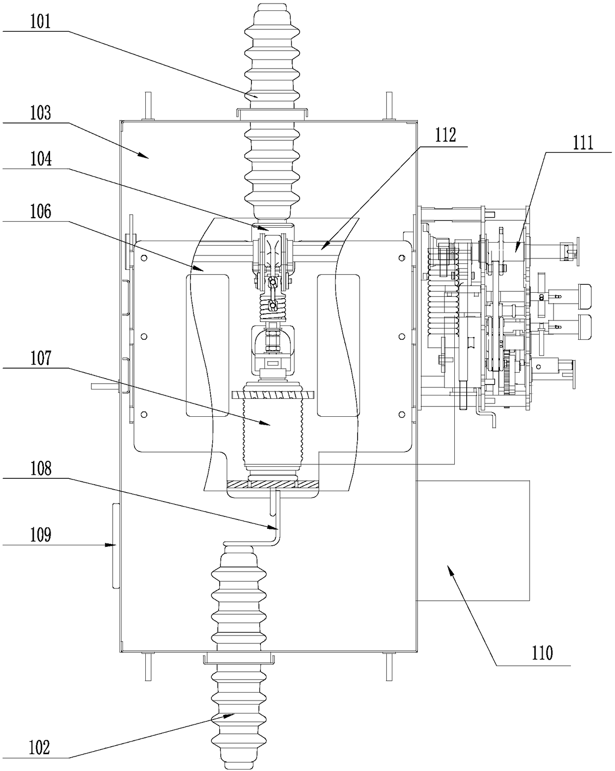
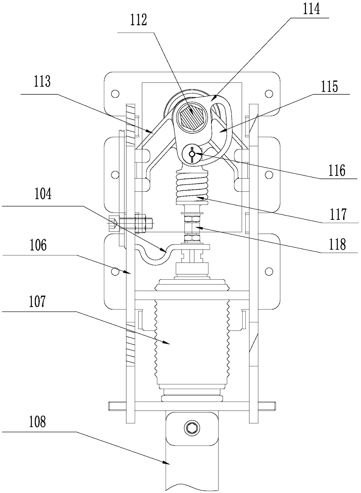
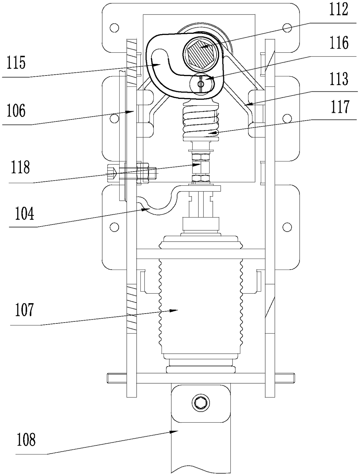
[0021] refer to Figure 1 to Figure 4 , a transformer neutral point grounding protection switch, comprising an incoming line insulating terminal 101 and an outgoing line insulating terminal 102, the incoming line insulating terminal 101 is connected to an upper copper bar 104, the outgoing line insulating terminal 102 is connected to a lower copper bar 108, and the upper copper bar The row 104 an...


PUM


Abstract

The invention discloses a grounding protection switch of a transformer neutral point. The switch is composed of an incoming wire insulated terminal and an outgoing wire insulated terminal; the incoming wire insulated terminal is connected with an upper copper bar; the outgoing wire insulated terminal is connected with a lower copper bar; and the upper copper bar and the lower bar are connected tothe upper end and the lower end of a switch core assembly. The switch core assembly consists of an operating mechanism, a driving assembly connected to the operating mechanism, and a vacuum arc-extinguishing chamber connected to the driving assembly; and the lower copper bar is connected to the lower end of the vacuum arc-extinguishing chamber. A transformer neutral point is connected with a ground conductor through the incoming insulated terminal and the outgoing insulated terminal of the switch to realize heavy-current effective grounding. Opening and closing are controlled by the switch core assembly.

Description

technical field [0001] The invention relates to the field of high-voltage power distribution equipment, in particular to a transformer neutral point grounding protection switch. Background technique [0002] The power system with a voltage level of 110kV and above in my country is an effective grounding system. The neutral point of some transformers is directly grounded. Not grounded. The neutral point of transformers currently in operation in my country usually adopts a graded insulation structure, which is characterized in that the insulation level of the neutral point is lower than the insulation level of the three-phase end outgoing line voltage level. In some power grids where the neutral point of the transformer is grounded, the ground short-circuit fault is a relatively common fault. When the system is struck by lightning or a ground fault occurs, and the neutral point grounded transformer trips, the power grid will become an ungrounded system. The rise of the sequen...

Claims


Application Information

Patent Timeline
IPC IPC(8): H02H7/04H02H9/08
CPCH02H7/04H02H9/08
Inventor 强卫许永军徐杰蔡志勇卫春晓钟冠池黄敏龙
Owner CHANGYUAN ELECTRIC TECH
Why Eureka
Try Eureka