
Enhanced piezomagnetic shoe energy collecting device

An energy harvesting and enhanced technology, which is applied in the field of extruded energy harvesting devices and footwear, can solve the problems of low energy conversion efficiency, poor structural reliability, troublesome installation, etc., and achieve large magnetic flux in the magnetic circuit and high energy conversion efficiency. High, compact and reliable effect

Pending Publication Date: 2018-09-28
ZHEJIANG UNIV OF TECH
View PDF4 Cites 2 Cited by
  • Summary
  • Abstract
  • Description
  • Claims
  • Application Information

AI Technical Summary

Problems solved by technology

[0006] In order to overcome the disadvantages of low energy conversion efficiency, poor structural reliability, and troublesome installation of existing shoes with power generation functions, the present invention provides an enhanced pressure magnetic shoe with high energy conversion efficiency, structural reliability, and easy installation. The shoe energy harvesting device has no moving parts, only elastic deformation parts or fretting parts, and only through small deformation and fretting to obtain a significant change in the magnetic field through the piezoelectric effect, the structure is compact and reliable; to achieve a closed magnetic circuit, through the closed magnetic The on-off of the road collects energy, and the energy conversion efficiency is high

Method used


Image

  • Enhanced piezomagnetic shoe energy collecting device
  • Enhanced piezomagnetic shoe energy collecting device
  • Enhanced piezomagnetic shoe energy collecting device

Examples


Embodiment Construction

[0029] The present invention will be further described below in conjunction with the accompanying drawings.

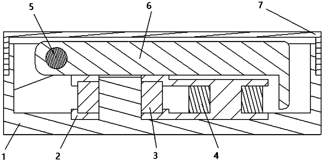
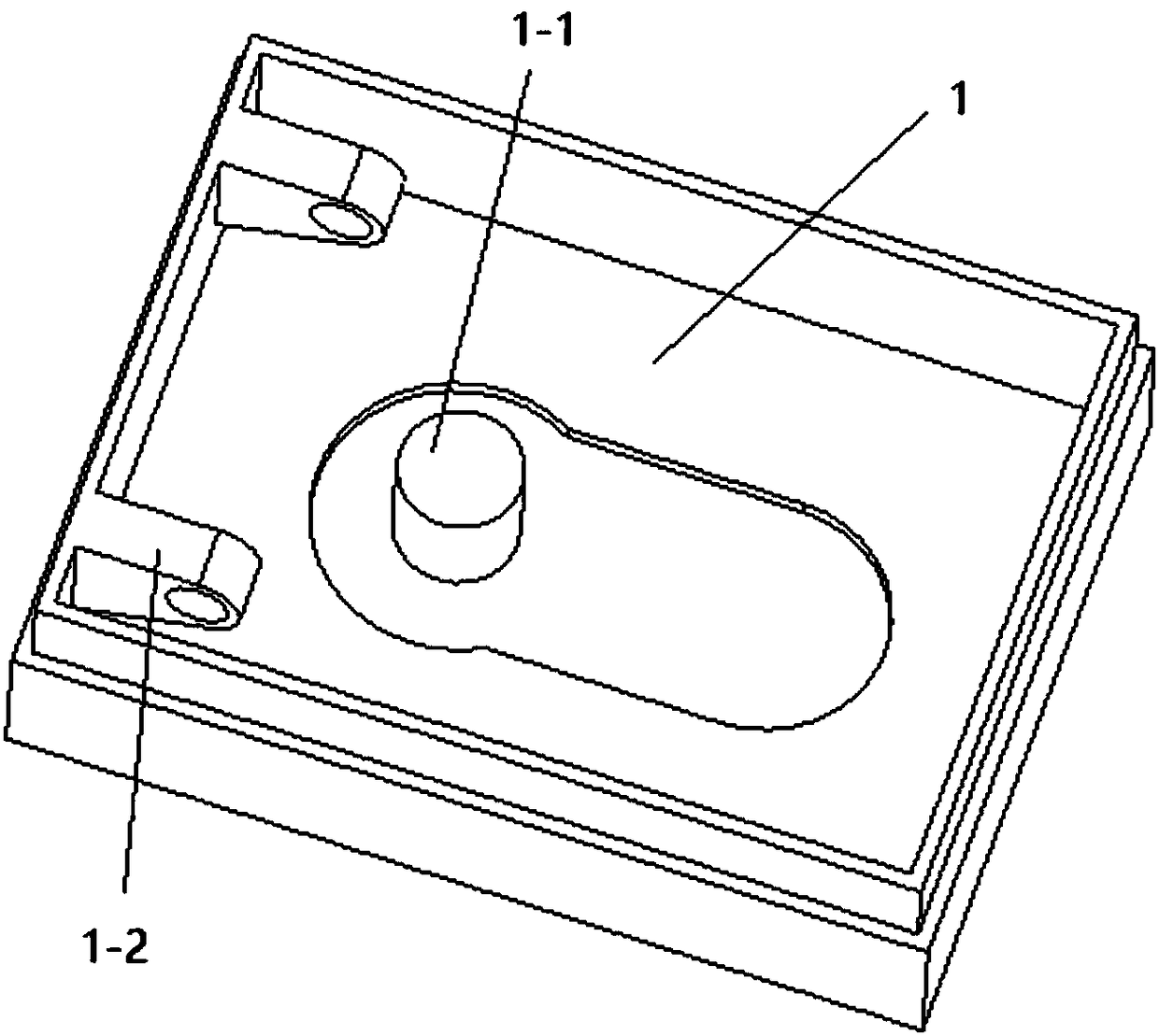
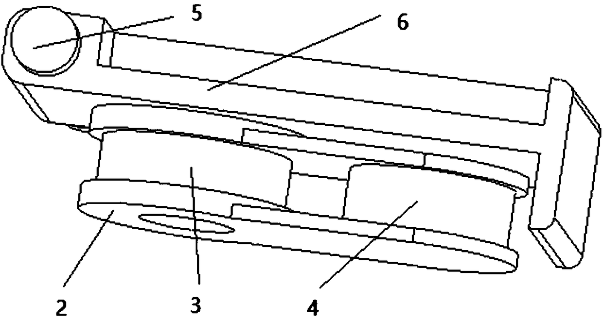
[0030] refer to Figure 1 to Figure 7 , an enhanced piezomagnetic shoe energy harvesting device, through the periodic movement of the foot on the ground and off the ground in the process of walking, through the electromagnetic device using the piezomagnetic effect, the slight mechanical energy of the human body is converted into electrical energy. Low-power wireless sensor nodes installed in the soles of the shoes are powered. The specific structure is described below:

[0031] The device has a rectangular base 1, see figure 1 , figure 2 and Figure 6 , made of non-magnetic plastic, non-magnetic, requires good toughness and wear resistance. There is an installation shaft 1-1 to the left of the middle part of the inner side of the base, and there is a depression around the installation shaft. There are two pressure rod bearings 1-2 on the left side wall of the ba...


PUM


Abstract

The invention relates to an enhanced piezomagnetic shoe energy collecting device. A mounting shaft is arranged to approach the left side of the middle part of the inner side of a pedestal and is surrounded by a recession part. Two pressing rod shaft supports are arranged at the left side wall of the pedestal; and a piezomagnetic magnet yoke is embedded into the bottom recession of the inner side of the pedestal and is fixed at the lower bottom of the pedestal. the piezomagnetic magnet yoke has an up-down symmetric structure; circular stepped holes are formed in the upper part and the lower part; small holes cooperate with the mounting shaft arranged at the pesetal at the outer side; and a cylindrical permanent magnet is installed between large holes at the inner sides of the two circular stepped holes of the piezomagnetic magnet yoke and the inner hole of the cylindrical permanent magnet cooperates with the mounting shaft arranged at the pesetal. An enamel-covered copper coil winds around the shaft between the upper and lower parts of the piezomagnetic magnet yoke and the two leading-out ends of the coils are connected with an energy collecting circuit. A pressing rod is fixed to the pressing rod shaft supports of the pedestal by a pressing rod shaft and is in contact with the upper surface of the mounting position of the piezomagnetic magnet yoke. The enhanced piezomagnetic shoe energy collecting device has advantages of high energy conversion efficiency, high structure reliability, and simple mounting.

Description

technical field [0001] The invention belongs to shoes, and relates to the field of electromagnetic energy harvesting devices in smart wear, in particular to a device that is placed in the sole of a shoe and collects energy through the extrusion of the sole by human walking. Background technique [0002] People are walking every day, and the human body uses its own biological energy to do its own exercise. The "walking volume" of healthy people is at least 4,000 steps per day. This activity volume is the basic amount of exercise for people. To promote health and prevent various chronic diseases, the standard should be raised to 7,000 steps. [0003] When a person walks, when the shoe hits the ground, the ground and the foot press against the sole; when the shoe leaves the ground, the squeeze disappears. Therefore, it has become a focus of research and invention to take certain measures to collect the mechanical energy of this periodic extrusion process and convert it into el...

Claims


Application Information

Patent Timeline
Patent Type & Authority Applications(China)
IPC IPC(8): H02K35/02A43B3/00
CPCH02K35/02A43B3/34
Inventor 张端孙莹
Owner ZHEJIANG UNIV OF TECH
Learn More