
Gravitational field distributed type bottom pouring method for numerical control gantry-type milling beam

A gravitational field, distributed technology, applied in the components of the mold, equipment for feeding molten metal into the mold, and casting molding equipment, etc. Stable filling and the effect of reducing metal oxidation

Inactive Publication Date: 2018-10-02
芜湖久弘重工股份有限公司
View PDF11 Cites 1 Cited by
  • Summary
  • Abstract
  • Description
  • Claims
  • Application Information

AI Technical Summary

Problems solved by technology

[0004] The object of the present invention is to provide a kind of numerically controlled gantry milling crossbeam under the gravity field dispersed type bottom pouring method, by adopting the gravity field under the dispersed bottom pouring method to carry out pouring, in order to solve the filling process that is proposed in the above-mentioned background technology is not stable, It is easy to produce splashing phenomenon, and the molten metal is more oxidized

Method used


Image

  • Gravitational field distributed type bottom pouring method for numerical control gantry-type milling beam
  • Gravitational field distributed type bottom pouring method for numerical control gantry-type milling beam
  • Gravitational field distributed type bottom pouring method for numerical control gantry-type milling beam

Examples


Embodiment 1

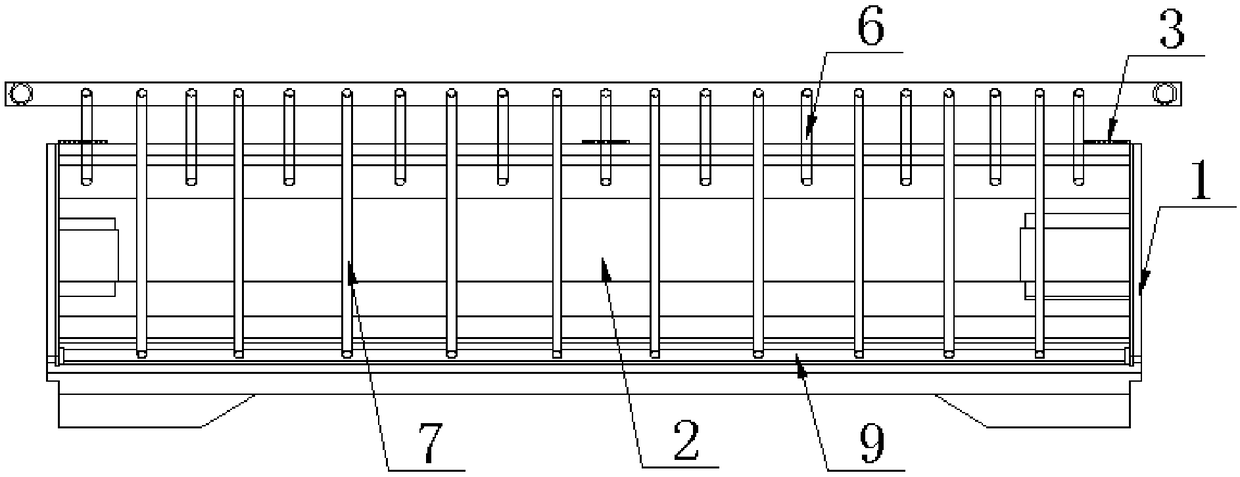
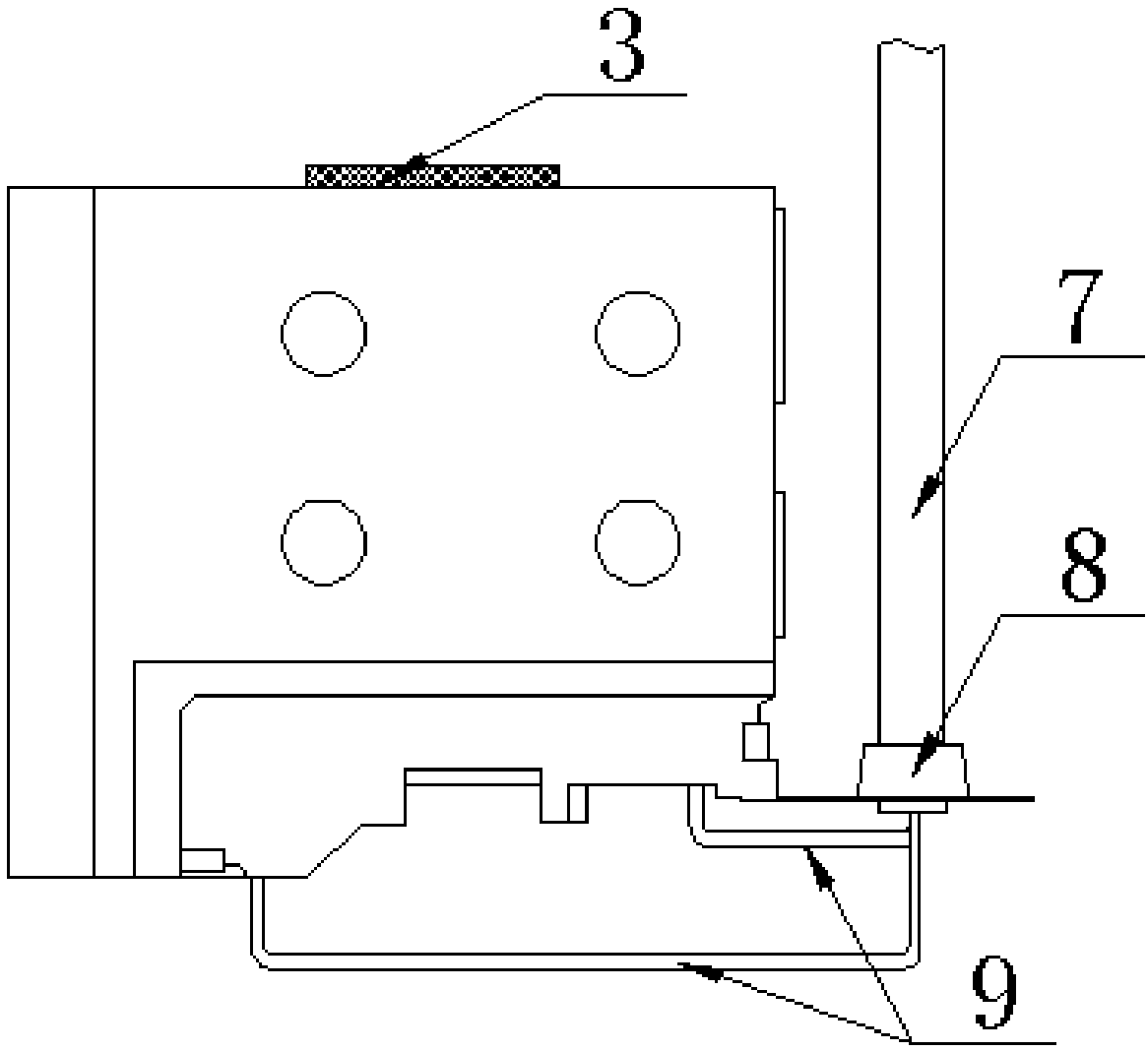
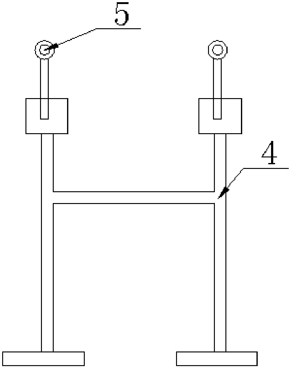
[0030] The present invention provides such Figure 1-4 Shown is a distributed bottom injection method under the gravity field of CNC gantry milling beam, and its specific operation steps are:

[0031] Step 1: Mold 1 installation: Fix the mold 1 on the workpiece pouring table;

[0032] Step 2: Manufacture of core bone 4: Pre-cast the core bone 4 and lifting lug 5 into an integral shape, so as to be used in the process of making the clay core 2;

[0033] Step 3: Making the clay core: making the clay core 2 with the precast overall shape of the core bone 4 and the lifting lug 5 as the skeleton;

[0034] Step 4: Hanging the core: use the hook 6 to hook the lifting lug 5, and hang the mud core 2 into the cavity of the mold 1;

[0035] Step 5: Pouring: The molten iron is introduced from the sprue 7, passed through the runner 8, dispersed into the cavity of the mold 1 through the ingate 9, and the pouring temperature is 1300°C. The pouring method of pouring and slow closing to the...

Embodiment 2

[0043] The difference from Example 1 is that in step five, the molten iron is introduced from the sprue 7, passed through the runner 8, dispersed through the ingate 9, and enters the cavity of the mold 1 in a balanced manner, wherein the pouring temperature is 1400 ℃, at the same time, adopt the pouring method of steady opening and fast injection, and slow closing to the top for pouring, that is, the iron nozzle is opened smoothly, and the pouring flow is opened from 1 / 3 to 1 / 2 of the opening to the Full flow, and after the opening of the flow, it can only accelerate steadily, and cannot close the flow. When the pouring height is 180-250mm after the opening is full, pour at full speed, and the injection speed should be greater than 350mm / min, so as to improve the surface quality. When the pouring height is 150-250mm, start to collect the flow to make the liquid level level and rise slowly. If the flow is too early, the surface quality of the workpiece will be poor. If the flow ...

Embodiment 3

[0045] The difference from Example 1 and Example 2 is that in step five, the molten iron is introduced from the sprue 7, passed through the runner 8, dispersed and evenly entered into the cavity of the mold 1 through the ingate 9, wherein the pouring The temperature is 1500°C. At the same time, the pouring method of steady opening and fast injection and slow closing is adopted for pouring, that is, the iron nozzle is opened smoothly, and the pouring flow is changed from 1 / 3 to 1 / 3 of the opening flow within 20 to 50 seconds. 2. The flow is opened to full flow, and after the flow is opened, it can only be accelerated steadily, and the flow cannot be closed. When it is fully opened and the distance from the pouring height is 180-250mm, pour at full speed, and the injection speed should be greater than 350mm / min, so as to improve the surface quality. , when the distance from the pouring height is ≥ 250mm, start to collect the flow to make the liquid level level and rise slowly. If...


PUM


Abstract

The invention discloses a gravitational field distributed type bottom pouring method for a numerical control gantry-type milling beam. The gravitational field distributed type bottom pouring method for the numerical control gantry-type milling beam specifically comprises the operation steps of 1, mould mounting, specifically, a mould is fixedly arranged on a workpiece pouring platform; 2, core barmanufacturing, specifically, a core bar and a lifting lug are precast into a whole so as to be conveniently used in the process of manufacturing a clay core; 3, clay core manufacturing, specifically,the whole formed by precasting the core bar and the lifting lug is used as a framework to be used for manufacturing the clay core; 4, core suspension, specifically, the lifting lug is hooked by a hook, and the clay core is suspended into a cavity of the mould; 5, pouring, specifically, molten iron is injected through sprues, passes through cross gates, is distributed and enters the cavity of themould through inner gates in a balanced mode; and 6, forming detection, specifically, the intensity of a formed workpiece is detected. Pouring is achieved through the gravitational field distributed type bottom pouring method, and the problems that mould filling is not stable, the splashing phenomenon is likely to occur, and much molten metal is oxidized in the pouring process of the prior art aresolved.

Description

technical field [0001] The invention relates to the technical field of pouring, in particular to a distributed bottom pouring method under the gravity field of a numerically controlled gantry milling beam. Background technique [0002] The CNC gantry milling beam is an important functional accessory designed for heavy-duty CNC machine tools and other types of machine tools. It is independent of the machine tool body and completes the linear feed function during the machining process of the CNC machine tool. At the same time, it can realize some auxiliary functions of the machine tool to ensure processing. Accuracy, improve production efficiency, reduce labor intensity. However, the existing CNC gantry milling beams are not filled smoothly during the pouring process, and splashing is easy to occur, and the molten metal is more oxidized. [0003] Therefore, it is necessary to invent a distributed bottom betting method under the gravity field of CNC gantry milling beam to solv...

Claims


Application Information

Patent Timeline
Patent Type & Authority Applications(China)
IPC IPC(8): B22D35/04B22C9/22B22C9/08
CPCB22C9/082B22C9/22B22D35/04
Inventor 艾明何文东姬唱
Owner 芜湖久弘重工股份有限公司
Learn More