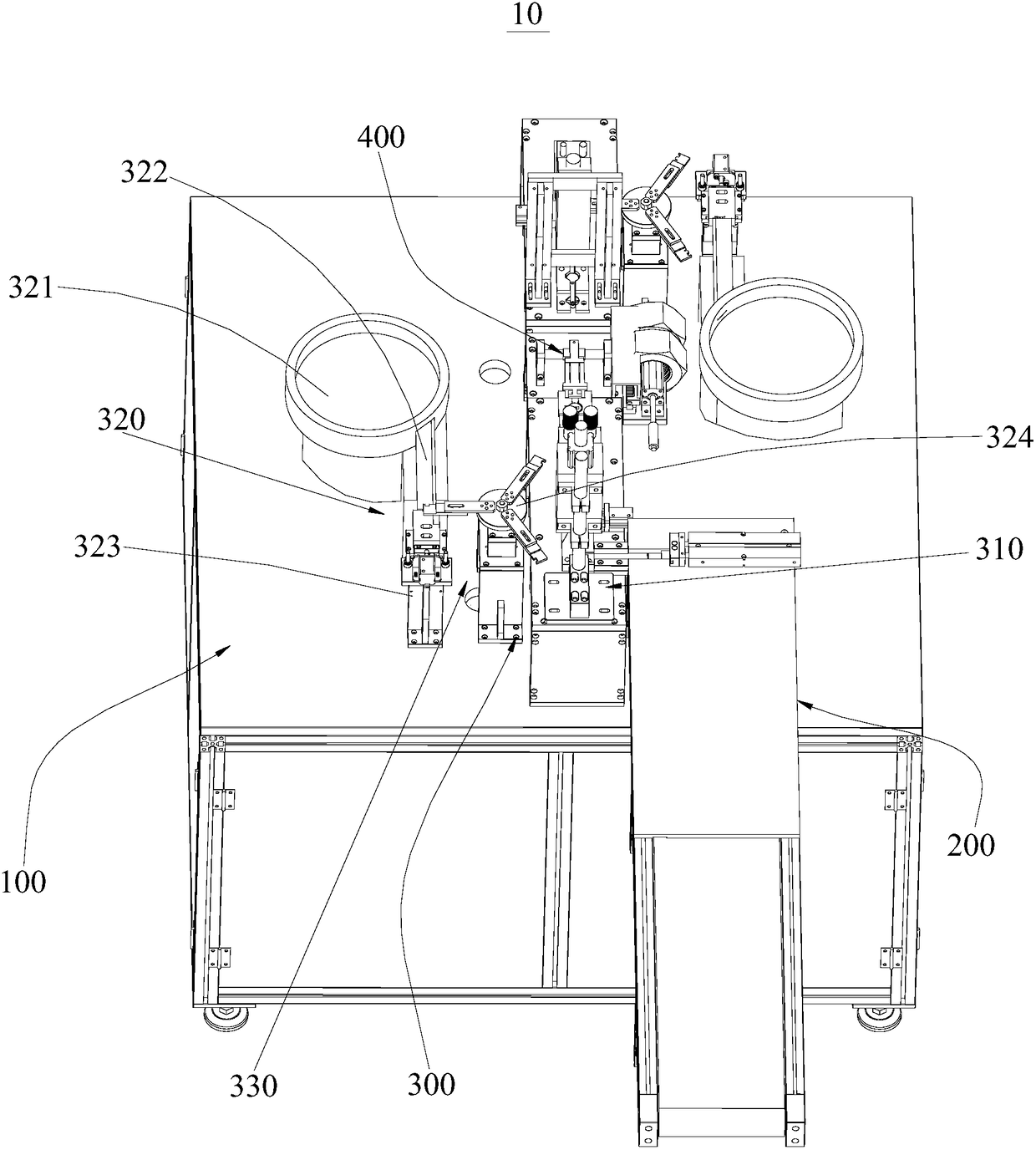
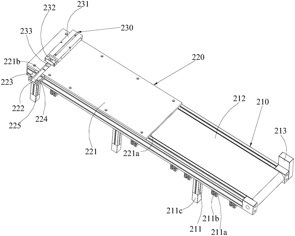
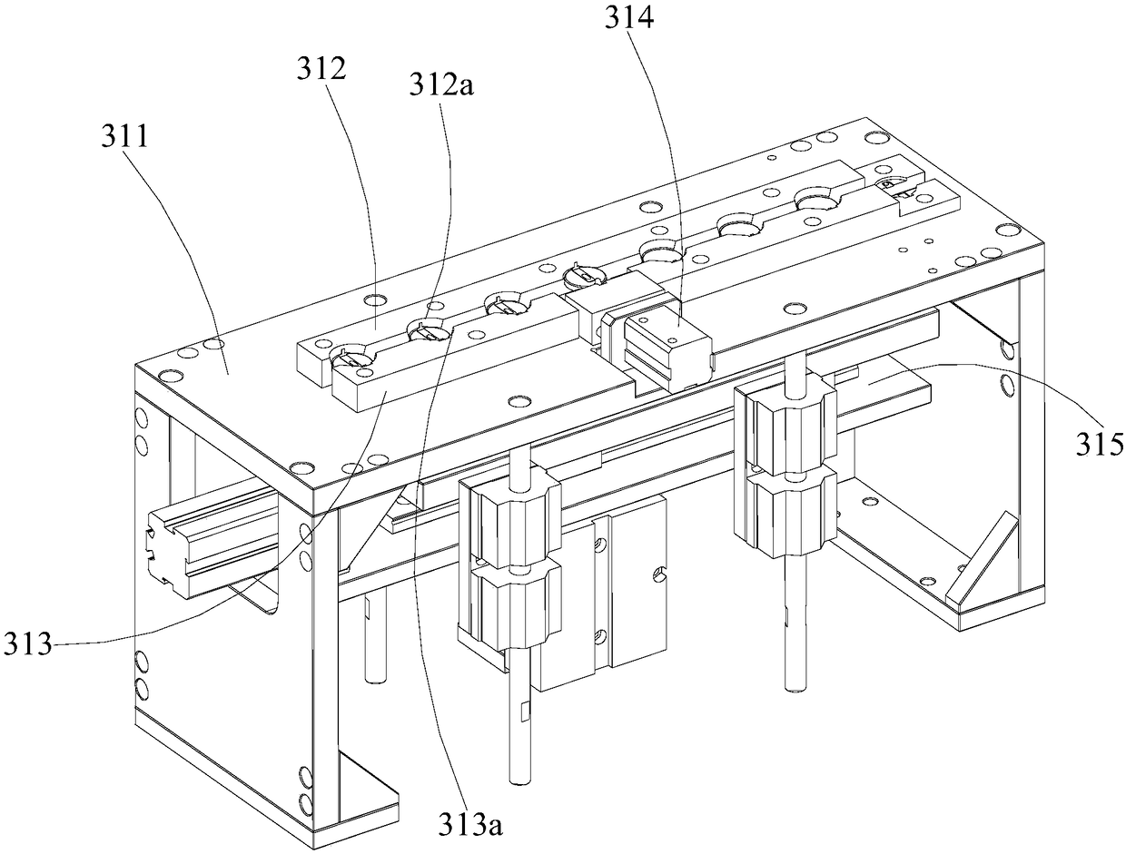
Chip transferring and spot-welding mechanisms and thermistor chip welding equipment with same

A chip welding and transfer point technology, applied in welding equipment, welding equipment, auxiliary welding equipment, etc., can solve problems such as difficult control of welding temperature, chip damage, and affecting the efficiency of chip production, so as to prevent excessive welding temperature and improve The effect of improving efficiency and accuracy

Pending Publication Date: 2018-10-02
惠州嘉科实业有限公司
View PDF6 Cites 5 Cited by
  • Summary
  • Abstract
  • Description
  • Claims
  • Application Information

AI Technical Summary

Problems solved by technology

[0003] During the production process of the thermistor, the chip of the thermistor needs to be welded. The traditional welding method is manual welding. The worker first welds the front of the thermistor chip through the welding torch, and then uses the welding torch to weld on the front of the thermistor chip. The reverse side of the thermistor chip is welded. At the same time, it is necessary to manually place the welded part on the corresponding welding position of the chip. In this way, the position of each chip after welding has a certain deviation, and the welding temperature during manual welding is not easy to control. , it is easy to cause damage to the chip, thus affecting the efficiency of chip production

Method used


Image

  • Chip transferring and spot-welding mechanisms and thermistor chip welding equipment with same
  • Chip transferring and spot-welding mechanisms and thermistor chip welding equipment with same
  • Chip transferring and spot-welding mechanisms and thermistor chip welding equipment with same

Examples


Embodiment Construction

[0035] In order to facilitate the understanding of the present invention, the present invention will be described more fully below with reference to the associated drawings. Preferred embodiments of the invention are shown in the accompanying drawings. However, the present invention can be embodied in many different forms and is not limited to the embodiments described herein. On the contrary, the purpose of providing these embodiments is to make the disclosure of the present invention more thorough and comprehensive.

[0036] It should be noted that when an element is referred to as being “fixed” to another element, it can be directly on the other element or there can also be an intervening element. When an element is referred to as being "connected to" another element, it can be directly connected to the other element or intervening elements may also be present. The terms "vertical," "horizontal," "left," "right," and similar expressions are used herein for purposes of ill...


PUM


Abstract

The invention provides chip transferring and spot-welding mechanisms and thermistor chip welding equipment with the chip transferring and spot-welding mechanisms. Each chip transferring and spot-welding mechanism comprises a chip welding and positioning device, a welded part feeding device and a chip welding device. Each welded part feeding device is installed on one side of the corresponding chipwelding and positioning device, each chip welding device is installed on the corresponding chip welding and positioning device, each chip welding and positioning device is used for performing weldingand positioning and transferring on chips, and each welded part feeding device is used for feeding welded parts to the corresponding chip welding and positioning device. The chip transferring and spot-welding mechanisms are provided with the chip welding and positioning devices, the welded part feeding devices and the chip welding devices, and thus feeding operation of the chips and the welded parts are completed; and meanwhile, the chips can be subjected to precise welding operation through the chip welding devices, the welding machining efficiency can be improved, the welding machining precision can also be improved, and damages to the chips due to the excessively high welding temperature are prevented.

Description

technical field [0001] The invention relates to the technical field of thermistor production and processing, in particular to a chip transfer spot welding mechanism and thermistor chip welding equipment. Background technique [0002] Thermistors are a type of sensitive components, which can be divided into positive temperature coefficient thermistors and negative temperature coefficient thermistors according to the temperature coefficient. A typical feature of a thermistor is that it is sensitive to temperature and exhibits different resistance values ​​at different temperatures. The higher the temperature of the positive temperature coefficient thermistor is, the greater the resistance value is, and the lower the resistance value of the negative temperature coefficient thermistor is when the temperature is higher, they are both semiconductor devices. [0003] During the production process of the thermistor, the chip of the thermistor needs to be welded. The traditional wel...

Claims


Application Information

Patent Timeline
Patent Type & Authority Applications(China)
IPC IPC(8): B23K31/02B23K37/00B23K37/04B23K37/047B23K37/02
CPCB23K31/02B23K37/00B23K37/0252B23K37/0435B23K37/047
Inventor 周大卫张少钰李鲲鹏
Owner 惠州嘉科实业有限公司
Why Eureka
Try Eureka