
Six-station bearing bush production machine tool

A six-station, bearing pad technology, applied in the direction of manufacturing tools, metal processing equipment, other manufacturing equipment/tools, etc., can solve the problems affecting the appearance quality of finished products, affecting the next process, and damage to the bearing pad surface, so as to facilitate rapid cooling of plastic shape, avoid inaccurate positioning, and the effect of small amount of metal rebound

Pending Publication Date: 2018-10-02
盐城市精派组合机床有限公司
View PDF0 Cites 6 Cited by
  • Summary
  • Abstract
  • Description
  • Claims
  • Application Information

AI Technical Summary

Problems solved by technology

[0003] With the improvement of the performance of steel materials, most of the bearing bushes are made of stainless steel at this stage, and the production process of the bearing bushes is usually directly pressed by hydraulic jacks, but the metal will have a certain amount of rebound after being bent by a sudden force, which leads to secondary problems. The product rate increases, but the traditional ditching process is prone to burrs, which must be processed separately in the later stage, wasting manpower and material resources, and most of the traditional fixing and transmission devices are mechanical fixing and conveyor belt transmission, and mechanical fixing will damage the surface of the bearing pad. Affect the appearance quality of the finished product, and the conveyor belt transmission will also easily cause the position of the bearing pad to shift, which will affect the progress of the next process. In view of the above problems, a six-station bearing pad production machine tool is proposed to solve the above problems

Method used


Image

  • Six-station bearing bush production machine tool
  • Six-station bearing bush production machine tool
  • Six-station bearing bush production machine tool

Examples


Embodiment Construction

[0017] The preferred embodiment of the present invention will be described in detail below in conjunction with accompanying drawing:

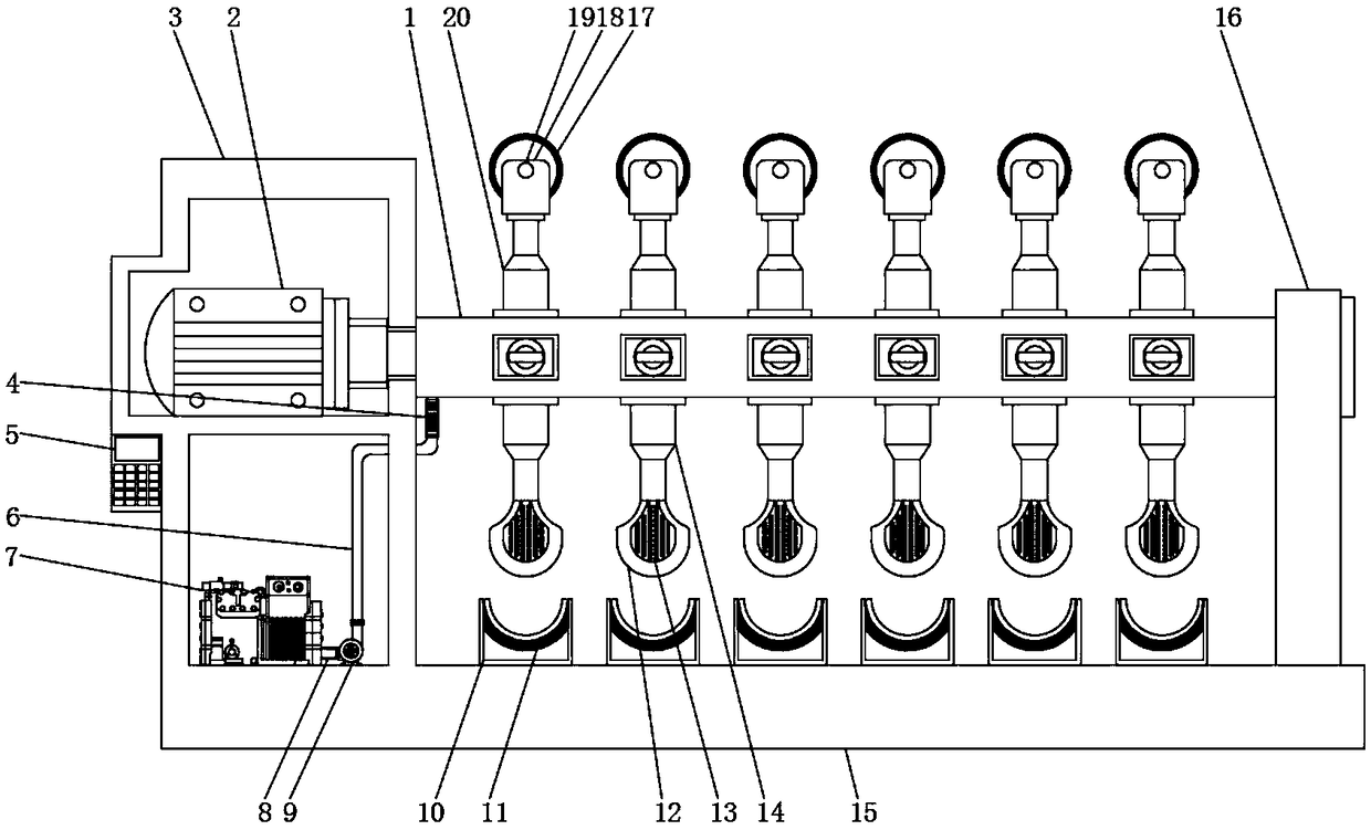
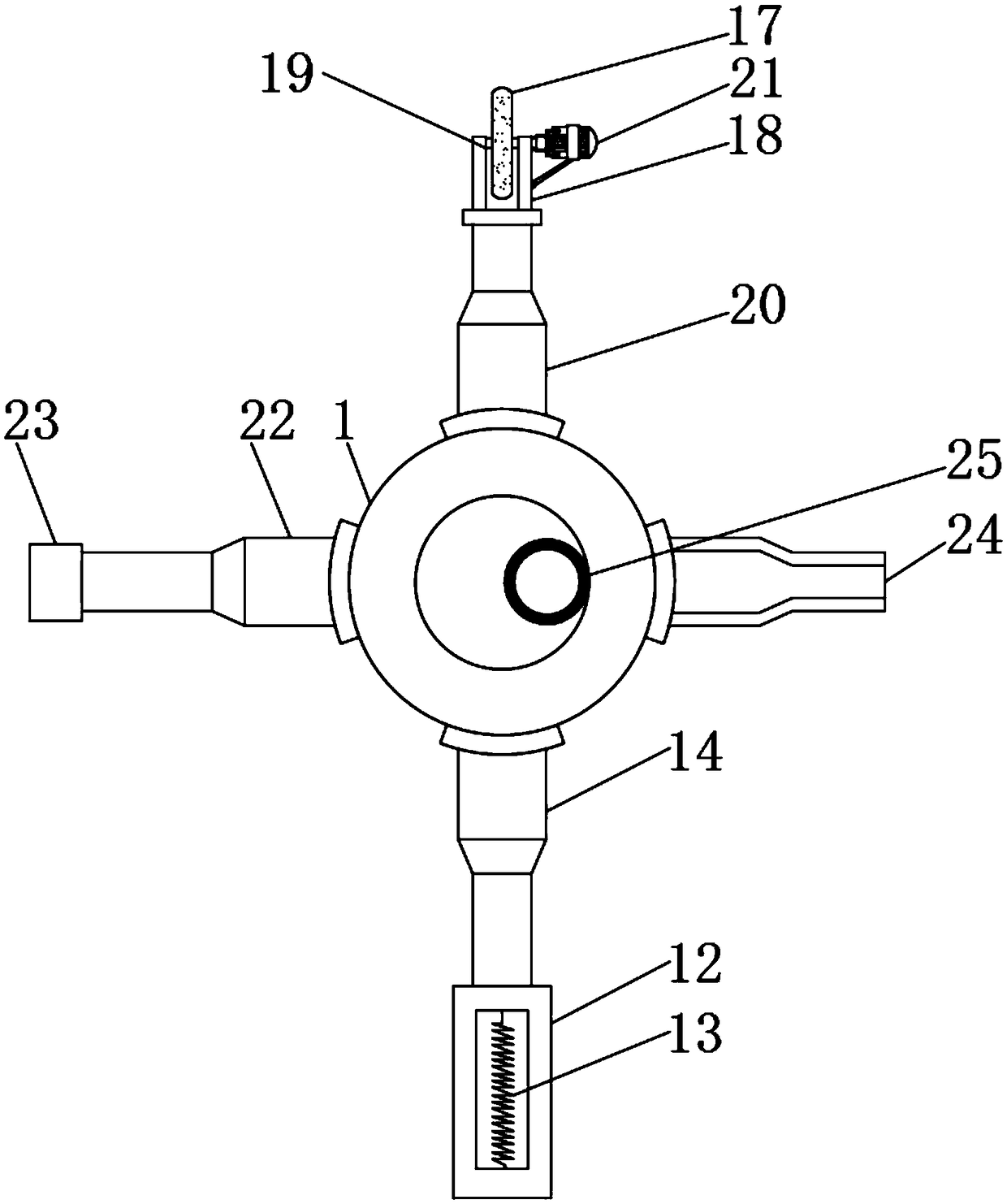
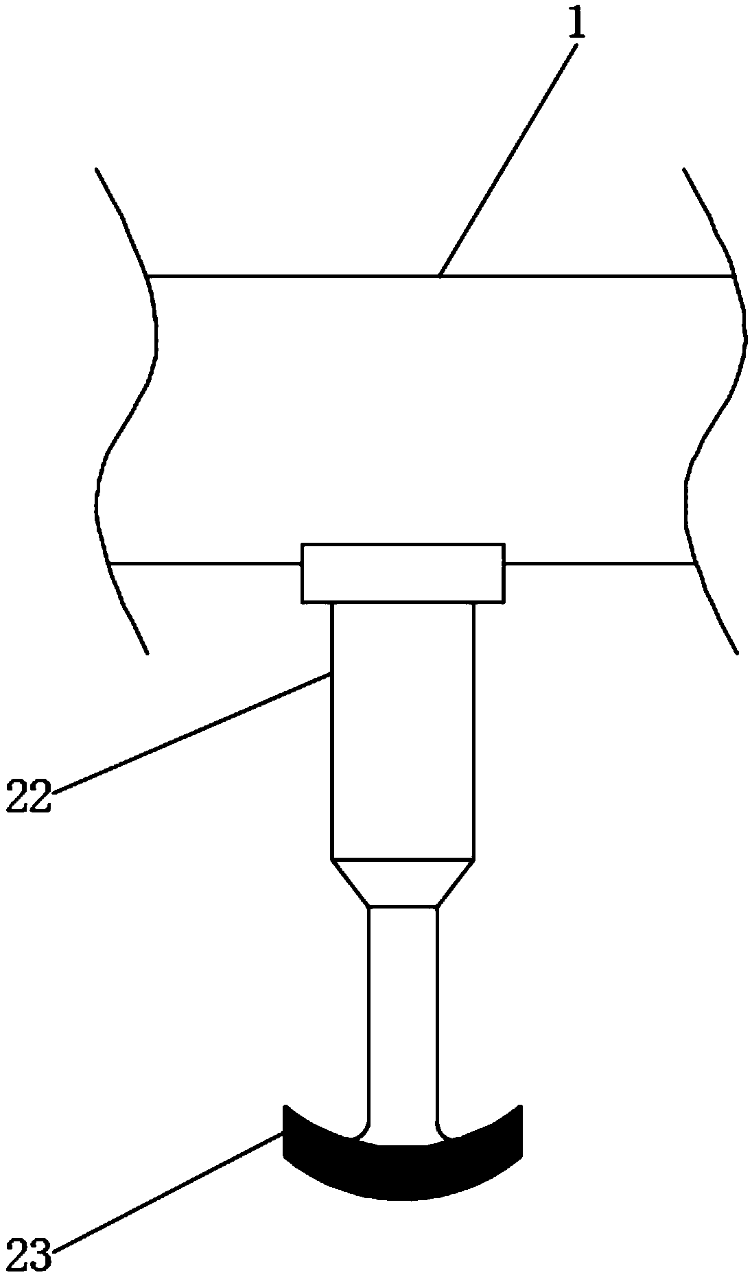
[0018] Please refer to Figure 1-3 , the present invention provides a technical solution: a six-station bearing pad production machine tool, including a rotating shaft 1 and a casing 3, one end of the rotating shaft 1 is provided with a casing 3, and the inside of the casing 3 is provided with a rotating motor 2, and one end of the rotating motor 2 runs through The surface of the chassis 3 is rotatably connected to the rotating shaft 1, and the surface of the rotating shaft 1 is welded with the pressure head telescopic rod 14, and the bottom surface of the pressure head telescopic rod 14 is welded with the pressure head 12, and the inside of the pressure head 12 is provided with a heating wire 13, and the pressure head telescopic rod 14 One side is welded with an electromagnet telescopic rod 22 on the surface of the rotating shaft 1, and one en...


PUM


Abstract

The invention discloses a six-station bearing bush production machine tool. The machine tool comprises a rotating shaft and a machine case; the machine case is arranged at one end of the rotating shaft, a rotating motor is arranged in the machine case, one end of the rotating motor penetrates the surface of the machine case and is rotatably connected with the rotating shaft, the surface of the rotating shaft is welded with a press head telescopic rod, a press head is welded to the bottom face of the press head telescopic rod, an electric heating wire is arranged in the press head, an electromagnet telescopic rod is welded to the position, on the surface of the rotating shaft, of one side of the press head telescopic rod, and an electromagnet is welded to one end of the electromagnet telescopic rod. The electric heating wire and a press base electromagnet are arranged, the electric heating wire is arranged in the press head, after powering on, the press head is heated, the heated presshead moves downwards through the press head telescopic rod, in the process of making contact with a bearing bush raw material, the bearing bush raw material is heated, due to the fact that most bearing bush materials are metal, in the process of making contact with the high-pressure press head, the strength is reduced, and extension is improved.

Description

technical field [0001] The invention relates to the technical field of bearing bush production, in particular to a six-station bearing bush production machine tool. Background technique [0002] The bearing pad is the contact part of the sliding bearing and the journal. The shape is a tile-like semi-cylindrical surface, which is very smooth. It is generally made of wear-resistant materials such as bronze and anti-friction alloy. In special cases, it can be made of wood, engineering plastics or rubber. production; [0003] With the improvement of steel properties, most of the bearing bushes are made of stainless steel at this stage, and the production process of the bearing bushes is usually directly pressed by hydraulic jacks, but the metal will have a certain amount of rebound after being bent by a sudden force, which leads to secondary problems. The increase in product rate, while the traditional ditching process is prone to burrs, which need to be processed separately in...

Claims


Application Information

Patent Timeline
IPC IPC(8): B23P23/00B24B55/06B24B55/02
CPCB23P23/00B24B55/02B24B55/06
Inventor 施志华
Owner 盐城市精派组合机床有限公司
Learn More