Method for transmitting time-frequency signal in optical fiber through polarized light

A technology for transmitting time and frequency signals, which is applied in multiplexing communication, transmission systems, electromagnetic wave transmission systems, etc., can solve the problem that the accuracy of optical fiber time transmission is difficult to further improve, and it is difficult to achieve sub-nanosecond level and higher precision optical fiber time transmission , optical fiber time transmission accuracy and other issues, to eliminate the impact of delay asymmetry, improve accuracy, and high time synchronization accuracy

Inactive Publication Date: 2018-10-02
SOUTHWEST UNIVERSITY FOR NATIONALITIES
View PDF5 Cites 5 Cited by
  • Summary
  • Abstract
  • Description
  • Claims
  • Application Information

AI Technical Summary

Problems solved by technology

[0005] It can be seen from Table 1 that: near the wavelength of 1550nm, the group delay difference after two wavelengths with an interval of 0.4nm transmission for 1000 kilometers can reach 6.6ns, that is, the asymmetry of the transmission link caused by dispersion can reach 6.6ns. The introduced delay asymmetry will have a serious impact on the accuracy of optical fiber time transfer, making it difficult to further improve the accuracy of optical fiber time transfer
[0006] To sum up, it is difficult to achieve sub-nanosecond and higher-precision fiber-optic time transfer technology, whether it is dual-fiber bi-directional or single-fiber bi-directional optical time transfer technology.

Method used


Image

  • Method for transmitting time-frequency signal in optical fiber through polarized light
  • Method for transmitting time-frequency signal in optical fiber through polarized light
  • Method for transmitting time-frequency signal in optical fiber through polarized light

Examples


Embodiment Construction

[0055] The present invention will be further described in detail below in conjunction with examples, but the implementation of the present invention is not limited thereto.

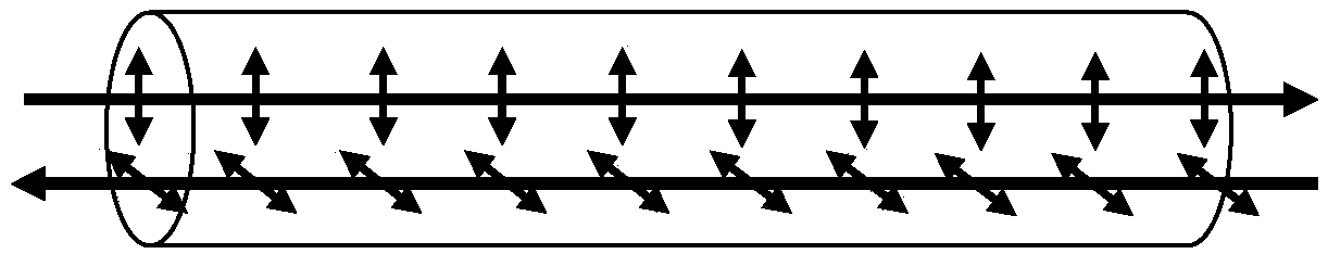
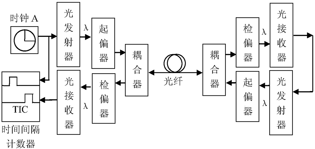
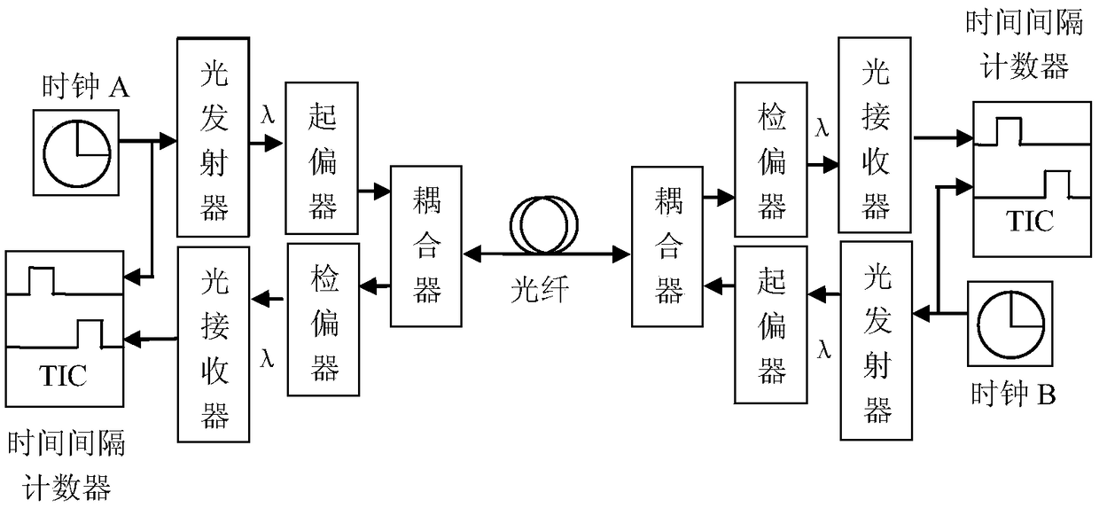
[0056] A method of using polarized light to transmit time and frequency signals in optical fibers. It is based on a single-fiber bidirectional optical fiber time transmission scheme. Two linearly polarized lights of the same wavelength are used to transmit time signals on a round-trip optical fiber link, thereby overcoming the need for round-trip optical fiber. The influence of delay asymmetry caused by fiber dispersion introduced by two different wavelengths on the link. In other words, since the two optical wavelengths transmitted back and forth are the same, the optical fiber transmission delay from station A to station B is T AB , And the optical fiber transmission delay T from station B to station A BA Exactly equal, namely T AB = T BA , Thereby improving the accuracy of time synchronization. In order...


PUM


Abstract

The invention discloses a method for transmitting a time-frequency signal in an optical fiber through polarized light. A single-fiber bidirectional optical fiber time transmission scheme acts as the basis; and two linearly polarized light of the same wavelength is applied to transmit the time signal on the back-and-forth optical fiber link so that the influence of the delay asymmetry caused by theoptical fiber dispersion introduced in the back-and-forth optical fiber link in case of using two light of different wavelengths to transmit the time signal can be overcome, the accuracy of optical fiber time signal transmission can be enhanced, and the time synchronization accuracy between the master and slave stations is enabled to be the subnanosecond level and even higher.

Description

Technical field [0001] The invention relates to the technical field of optical fiber time-frequency transmission, in particular to a method for transmitting time-frequency signals in an optical fiber by using polarized light. Background technique [0002] With the development of communication technology, optical fiber communication networks are developing in the direction of high speed, large capacity, and low latency. Therefore, the requirements on the time and frequency synchronization accuracy of the optical fiber communication network are correspondingly improved. The existing optical fiber time transfer technology mainly adopts two-fiber bidirectional and single-fiber bidirectional transfer modes. In the dual-fiber bidirectional optical time transfer solution, the IEEE 1588v1 and IEEE 1588v2 time synchronization standards promulgated by the IEEE organization are usually used. Due to the influence of the number of hops of optical fiber network nodes and the transmission del...

Claims


Application Information

Patent Timeline
Patent Type & Authority Applications(China)
IPC IPC(8): H04B10/2569H04B10/61H04J3/06H04J3/16
CPCH04B10/2569H04B10/6162H04J3/0682H04J3/1664
Inventor 彭良福黄勤珍苗峰
Owner SOUTHWEST UNIVERSITY FOR NATIONALITIES
Why Eureka
Try Eureka