Method for controlling flow guiding sand to enter tundish in continuous casting process

A process control and sand drainage technology, applied in the field of iron and steel continuous casting, can solve the problems of poor operation controllability, cumbersome operation, complex equipment, etc., and achieve the effect of promoting molten steel stirring, ensuring automatic pouring, and ensuring the quality of casting billets

Active Publication Date: 2018-10-09
NORTHEASTERN UNIV
View PDF9 Cites 1 Cited by
  • Summary
  • Abstract
  • Description
  • Claims
  • Application Information

AI Technical Summary

Problems solved by technology

A small number of iron and steel enterprises manually pick up part of the drainage sand before the molten steel flows out of the ladle. Although this partially reduces the amount of drainage sand flowing into the tundish, a considerable amount of drainage sand will still enter the tundish; Sand has the following disadvantages: ①The operation is poorly controllable and the labor intensity of workers is high; ②There are potential safety hazards
This patent has the following shortcomings: complex equipment, high cost, and cumbersome operation; no specific operating parameters are given, which is of little significance for practical application guidance on the spot; no consideration is given to the narrow space between the ladle and the tundish, and then the drainage sand is installed. Devices and other devices will affect the normal pouring production and are not suitable for large-scale production applications on site
[0005] At present, there is no effective method that can completely prevent the drainage sand from flowing into the tundish, and the pollution to the molten steel caused by the drainage sand flowing into the tundish cannot be completely eliminated. The present invention proposes a method for controlling the drainage sand into the tundish during the continuous casting process. It can completely solve the technical problem of drainage sand flowing into the tundish, and has low cost and easy operation, which is of great significance to the stable production of high-quality steel

Method used


Image

  • Method for controlling flow guiding sand to enter tundish in continuous casting process
  • Method for controlling flow guiding sand to enter tundish in continuous casting process

Examples


Embodiment 1

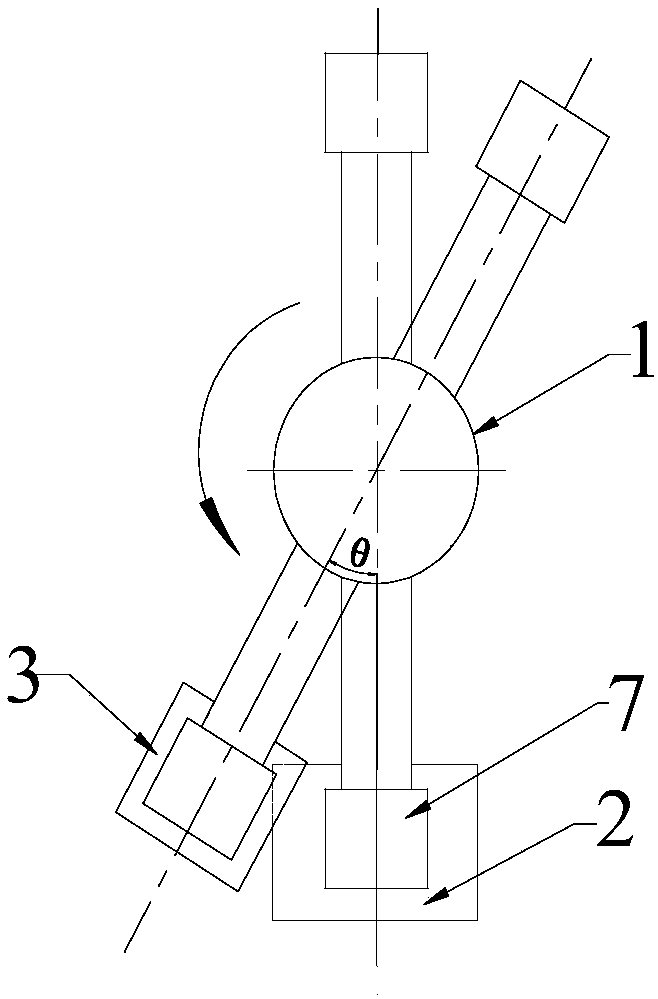
[0028] A method for controlling drainage sand to enter the tundish during continuous casting, such as figure 1 and 2 As shown, adopt 60 tons of ladles in the present embodiment; Specifically comprise the steps:

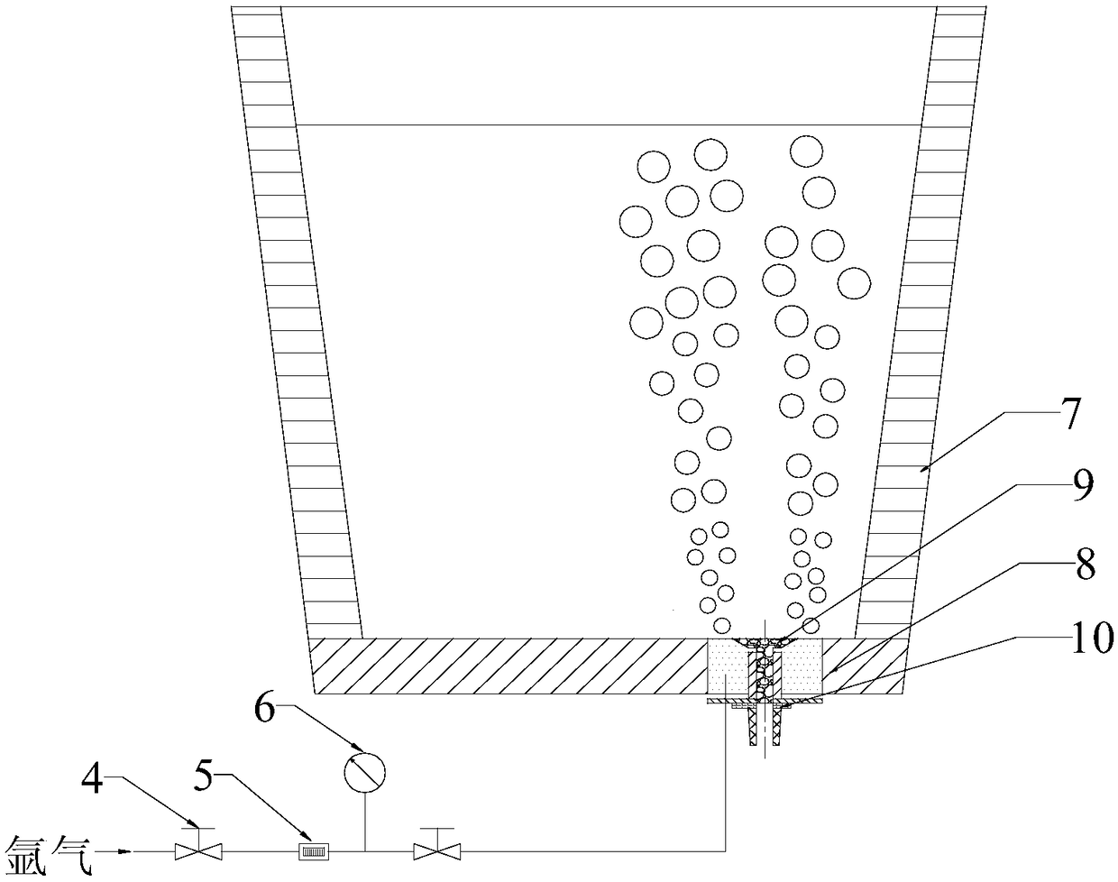
[0029] Step 1: 5 minutes before the pouring of the previous ladle is completed, blow argon gas into the molten steel in the ladle through the vent block 8 at the bottom of the ladle to the ladle 7 with drainage sand at the standby position of the ladle turret 1; when the ladle 7 When the ladle turret 1 rotates to an angle of 20° with the ladle pouring position, stop the rotation; among them: the pressure of blowing argon gas is: 0.3MPa, the flow rate is 5Nm 3 / h;

[0030] Step 2: Continuously blowing in argon gas to increase the temperature of the molten steel within 10cm directly above the vent block 8 by 2-5°C, and make the temperature of the molten steel in the ladle even. Place the steel scrap tank 3 under the sliding nozzle 10 of the ladle 7, open the sliding ...

Embodiment 2

[0037] A method for controlling drainage sand to enter the tundish during continuous casting, such as figure 1 and 2 As shown, adopt 120 tons of ladles in the present embodiment; Specifically comprise the following steps:

[0038] Step 1: 6 minutes before the pouring of the previous furnace ladle is completed, blow argon into the molten steel in the ladle through the breathable nozzle block 8 at the bottom of the ladle to the ladle 7 with drainage sand at the standby position of the ladle turret 1; when the ladle 7. When the ladle turret 1 rotates to an angle of 30° with the ladle pouring position, stop the rotation; among them: the pressure of blowing argon is: 0.4MPa, and the flow rate is 15Nm 3 / h;

[0039] Step 2: Continuously blowing in argon gas to increase the temperature of the molten steel within 10cm directly above the vent block 8 by 2-5°C, and make the temperature of the molten steel in the ladle even. Place the steel scrap tank 3 under the sliding nozzle 10 of ...

Embodiment 3

[0046]A method for controlling drainage sand to enter the tundish during continuous casting, such as figure 1 and 2 As shown, adopt 180 tons of ladles in the present embodiment; Specifically comprise the following steps:

[0047] Step 1: 10 minutes before the pouring of the previous ladle is completed, blow argon gas into the molten steel in the ladle through the breathable nozzle block 8 at the bottom of the ladle when the ladle 7 with drainage sand is in the standby position of the ladle turret 1; when the ladle 7. When the ladle turret 1 rotates to an angle of 50° with the ladle pouring position, stop the rotation; among them: the pressure of blowing argon is: 0.45MPa, and the flow rate is 25Nm 3 / h;

[0048] Step 2: Continuously blowing in argon gas to increase the temperature of the molten steel within 10cm directly above the vent block 8 by 2-5°C, and make the temperature of the molten steel in the ladle even. Place the scrap steel tank 3 under the sliding nozzle 10 o...


PUM


Abstract

The invention discloses a method for controlling flow guiding sand to enter tundish in the continuous casting process and belongs to the field of continuous casting of iron and steel. The method includes the steps that firstly, before casting of a previous furnace steel ladle is completed, for a steel ladle without casting starting, located on a standby position of a steel ladle revolving platformand provided with flow guiding sand, inert gas is blown into molten steel through a breathable water gap base brick at the bottom of the steel ladle; and when the steel ladle rotates on the steel ladle revolving platform till an angle with a steel ladle casting position is 20 degrees to 50 degrees, rotation stops; secondly, a waste steel groove is placed below a steel ladle water gap, due to continuous gas blowing in the period from the time when it is started to blow in the inert gas to the time when rotation stops for the first time, the temperature of molten steel over the breathable watergap base brick is made to increase by 2-5 DEG C, a sliding water gap is opened for the first time, and the flow guiding sand and an extremely small amount of molten steel are discharged; and when allthe flow guiding sand is discharged, the sliding water gap is closed; and thirdly, it is kept to blow in the inert gas, the steel ladle is fast rotated to the casting position, and is connected witha large ladle long water gap, the sliding water gap is opened for the second time, and normal casting starting starts; and after normal casting starting of the steel ladle starts, it is stopped to blow in the inert gas.

Description

technical field [0001] The invention belongs to the field of continuous casting of iron and steel, and in particular relates to a method for controlling drainage sand to enter a tundish in a continuous casting process. Background technique [0002] In the continuous casting production process, it is usually necessary to use ladle drainage sand for drainage, that is, add drainage sand to the upper nozzle of the ladle. When the sliding nozzle slide plate is opened, the drainage sand will fall due to the pressure of the molten steel, and the molten steel will automatically flow out with the drainage sand. flow out. After the molten steel is automatically poured, the drainage sand will also enter the tundish. Due to the large size of the drainage sand, if it cannot be removed in time, it will react with the molten steel to form large inclusions in the steel, which will seriously pollute the molten steel and significantly deteriorate the casting. Blank and product quality. [0...

Claims


Application Information

Patent Timeline
Patent Type & Authority Applications(China)
IPC IPC(8): B22D11/10B22D11/11
CPCB22D11/10B22D11/11
Inventor 郑淑国邹琦朱苗勇
Owner NORTHEASTERN UNIV
Why Eureka
Try Eureka