A three-phase separator with continuous exhaust, intermittent slag discharge and backwash

A three-phase separator and backwashing technology, which is applied in separation methods, filtration separation, chemical instruments and methods, etc., can solve the leakage of slag discharge screw blades and rotary sealing valves, leakage of slag discharge screw and rotary sealing valves, and affect equipment Stability and other issues, to achieve stable equipment operation, stabilize system pressure, and realize the effect of automatic positive and negative flushing

Active Publication Date: 2020-05-22
XI AN JIAOTONG UNIV
View PDF2 Cites 0 Cited by
  • Summary
  • Abstract
  • Description
  • Claims
  • Application Information

AI Technical Summary

Problems solved by technology

[0005] These solutions in the prior art are not completely satisfactory, because there is pressure inside the cavity, the slag discharge screw at the bottom and the rotary sealing valve will leak, which will affect the stability of equipment operation
At the same time, if the filter screen is clogged when the solution of the above prior art is used, the internal filter residue can only be cleaned by scraping. If the aperture of the filter screen is blocked, the equipment will stop running.
Furthermore, the solid residue removal part is only a vertical discharge pipe, and the space is narrow. When there is too much slag, it is easy to be squeezed and agglomerated, which will cause the internal pressure of the vertical discharge pipe cavity to increase, and the discharge pipe at the bottom will Slag spiral blades and rotary sealing valves will leak, which will affect the stability of equipment operation

Method used


Image

  • A three-phase separator with continuous exhaust, intermittent slag discharge and backwash
  • A three-phase separator with continuous exhaust, intermittent slag discharge and backwash
  • A three-phase separator with continuous exhaust, intermittent slag discharge and backwash

Examples


Embodiment Construction

[0031] The present invention will be further described in detail below in conjunction with specific embodiments, which are explanations of the present invention rather than limitations.

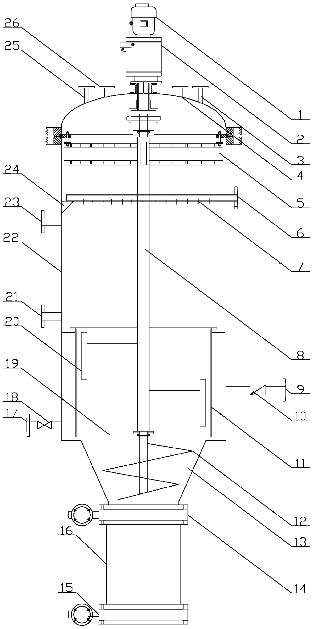
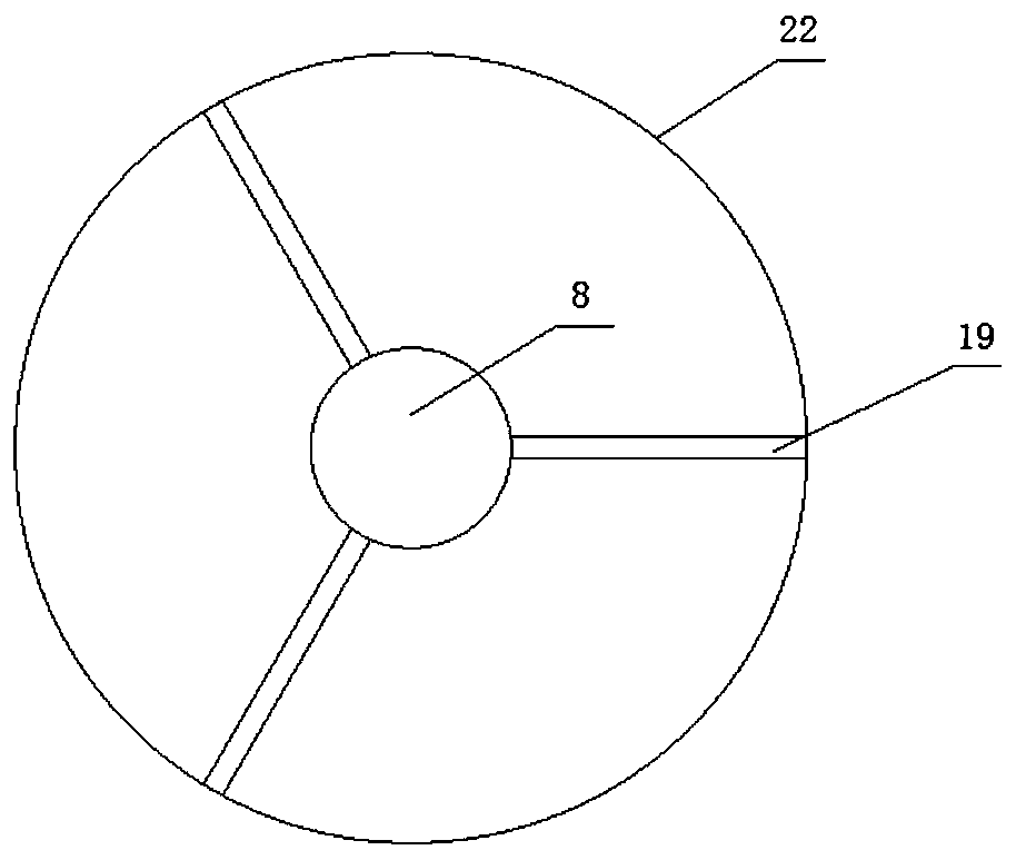
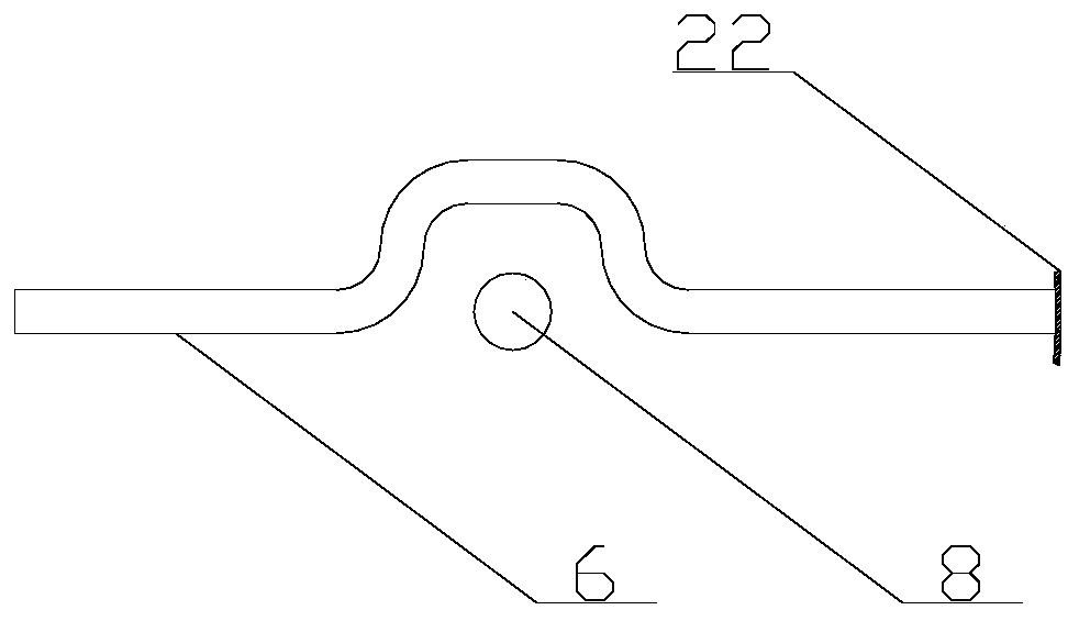
[0032] Such as Figure 1 ~ Figure 3 As shown, a three-phase separator with continuous exhaust, intermittent slagging and backwash disclosed in the present invention includes a cylinder 22, a motor 1 and a reducer 2 are installed above the cylinder 22, and the motor 1 is connected through the reducer 2 The rotating shaft 8 drives the rotating shaft 8 to rotate. The rotating shaft 8 is arranged on the central axis of the cylinder body 22. The upper middle part of the cylinder body 22 is provided with a feed pipe 6. The feed pipe 6 is the liquid inlet containing gas-solid impurities. The feed pipe 6 There are a number of nozzles 7 on the tube wall, and the horizontal feed tube 6 divides the cylinder into upper and lower parts. The upper part of the feed tube 6 is the gas-liquid separation part, ...


PUM


Abstract

The invention discloses a backwash three-phase separator for continuous exhaust and intermittent deslagging and belongs to the technical field of filtering separation equipment. The backwash three-phase separator comprises a cylinder body, wherein a feeding pipe is horizontally arranged in the cylinder body; the lower part of the feeding pipe is a liquid-solid separating part; an annular filter screen is arranged in a bottom cavity of the liquid-solid separating part; a backwash mechanism and a liquid draining outlet are formed in the outer wall, corresponding to the position of the filter screen, of the cylinder body; an intermittent deslagging mechanism is arranged below the liquid-solid separating part; and when the annular filter screen is blocked, the backwash mechanism can blow air into the cylinder body for blowing off residues on the annular filter screen, so that regeneration of the annular filter screen is realized, continuous operation of equipment is ensured and further continuous exhaust can be realized. Solid residues are downward pushed by a loosening screw, and intermittent discharge of slag is controlled by intermittent opening of upper and lower valves, so that extrusion and aggregation of the slag are prevented, further the phenomenon of sharp increase of internal pressure of the cylinder body is effectively avoided, and stable operation of equipment is ensured.

Description

technical field [0001] The invention belongs to the technical field of filtration and separation equipment, and in particular relates to a three-phase separator with continuous exhaust, intermittent slag discharge and backwashing. Background technique [0002] With the improvement of people's living standards, the scale of urban sewage construction in the country has developed rapidly. Sludge is a by-product of sewage treatment. Every 10,000 tons of sewage treated produces an average of 5.6 tons of wet sludge with a moisture content of 80%. In 2016, the output of urban sludge Exceeded 40 million tons. Supercritical water oxidation technology uses supercritical water (Tc≥374.95℃, Pc≥22.064MPa) as a reaction medium to treat municipal sludge as an environmental protection technology, which can completely realize the harmlessness of municipal sludge. In the process of supercritical water oxidation of municipal sludge, CO will be generated 2 , N 2 and other small molecular gas...

Claims


Application Information

Patent Timeline
Patent Type & Authority Patents(China)
IPC IPC(8): C02F11/08C02F11/121B01D29/94B01D29/64B01D35/01
CPCB01D29/6476B01D29/94B01D36/001C02F11/086C02F11/121C02F2103/001
Inventor 王树众杨闯宋文瀚张熠姝徐甜甜王栋李艳辉
Owner XI AN JIAOTONG UNIV
Why Eureka
Try Eureka