Highly versatile and easy-to-assemble high-strength support assembly structure

A combined structure, high-strength technology, applied in the support structure of photovoltaic modules, the fixed base/support of solar collectors, the connection of rods, etc. Corrosion reduction and other problems, to achieve the effect of high convenience

Inactive Publication Date: 2018-10-09
尚稚程
View PDF6 Cites 3 Cited by
  • Summary
  • Abstract
  • Description
  • Claims
  • Application Information

AI Technical Summary

Problems solved by technology

[0005] The fixing method of horizontal and longitudinal beams W and L is mostly by welding: when erecting the bracket, additional welding equipment must be prepared to the assembly site, or welded in the factory in advance and then transported to the site, whether it is the transportation process or the general use of steel In addition, the welding quality of the horizontal and longitudinal beams W and L is different due to personal technology, and the welding process is likely to cause the coating on the surface of the steel to melt due to high temperature (not shown in the figure) ), resulting in the corrosion of the weld bead along the welding in the future and affecting the strength of the steel
[0006] The way of erecting the horizontal and longitudinal beams W and L: Generally, C-shaped steel can be divided into one A-side A, two corresponding and parallel B-sides B and two C-sides C according to its composition structure; each B-side B is The long end of A side A and its corresponding long end are respectively bent and extended, and each C side C is separately arranged on the B side B, and the two long ends of B are bent and extended to form a C-shaped steel structure with an open side CX (such as Figure 15 shown); in order to conveniently fix the beam W and the longitudinal beam L with screws, screw holes S are usually provided at equal distances from the side A of the C-shaped steel A and the side B of the B side, which leads to more screw holes S and more production efficiency In addition to being worse, the rigidity and corrosion resistance of C-shaped steel are seriously reduced, and it is easy to be damaged, deformed or corroded by external forces. In addition, the terrain where the bracket is assembled is difficult to grasp in advance. If it is used on the A surface of C-shaped steel The method of preset screw hole S position on side A and side B cannot be used to fine-tune the mutual position of C-shaped steel
[0007] In addition, whether the C-shaped steel is used as the support beam W or the longitudinal beam L, it is assembled by overlapping the A side A and the B side B correspondingly. The side A of A is seriously deformed due to severe exertion (such as Figure 16 As shown), if the force can be applied to the A side of the C-shaped steel, A will be less prone to deformation. The reason is that when the A side A is stressed, the B side B located on its two sides will be hard at the same time, and the force is more dispersed. It is not easy to deform, and it can be proved in the same way that if the C side C corresponding to the A side can be used as a force-bearing surface, the force can also be distributed to the B side B. However, the C side C must not be able to drill the screw hole S because it has an open side CX As the locking side, the industry can only choose the assembly method of B side B force
[0008] As mentioned above, it is known that the C-shaped steel has at least one opening side CX, so it is the dilemma of the locking side, so that the open side CX of the C-shaped steel cannot be covered by objects. After long-term use, it is found that the inside of the C-shaped steel is prone to rust and affects its rigidity. Take the installation of solar panels as an example, most of them are installed on the seaside or in industrial areas, and most of the air contains highly corrosive substances (such as sulfur dioxide (SO2) or chlorine salt (NO2), etc.) Blowing in from the open side CX of the C-shaped steel (because the open side CX has no shelter) results in the deposition of highly corrosive substances at the inner corners of the C-shaped steel (such as Figure 17 Shown) lead to corrosion at this place, and in severe cases, the cross-sectional area of ​​C-shaped steel will be reduced and the original strength will be lost.

Method used


Image

  • Highly versatile and easy-to-assemble high-strength support assembly structure
  • Highly versatile and easy-to-assemble high-strength support assembly structure
  • Highly versatile and easy-to-assemble high-strength support assembly structure

Examples


Embodiment Construction

[0040] In order to achieve the above-mentioned purpose and effect, the technical means and the structure adopted by the present invention are hereby described in detail with respect to the preferred embodiments of the present invention.

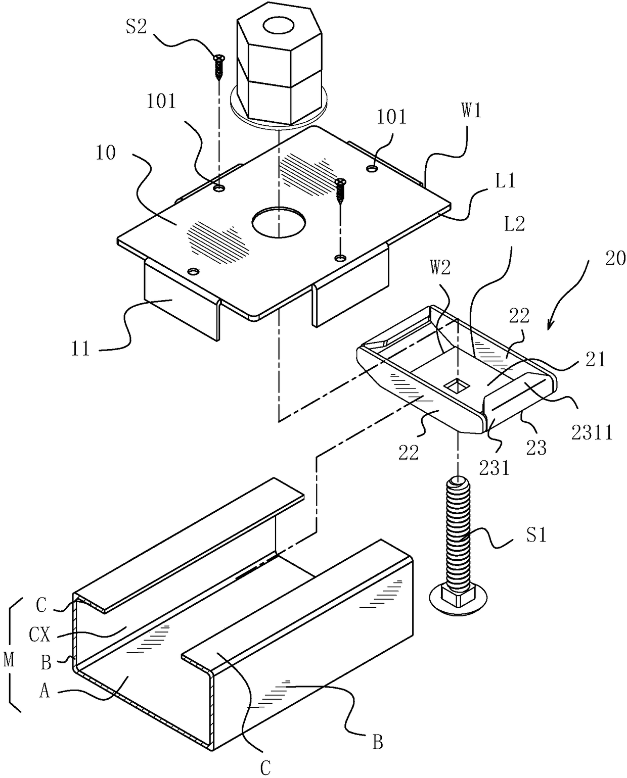
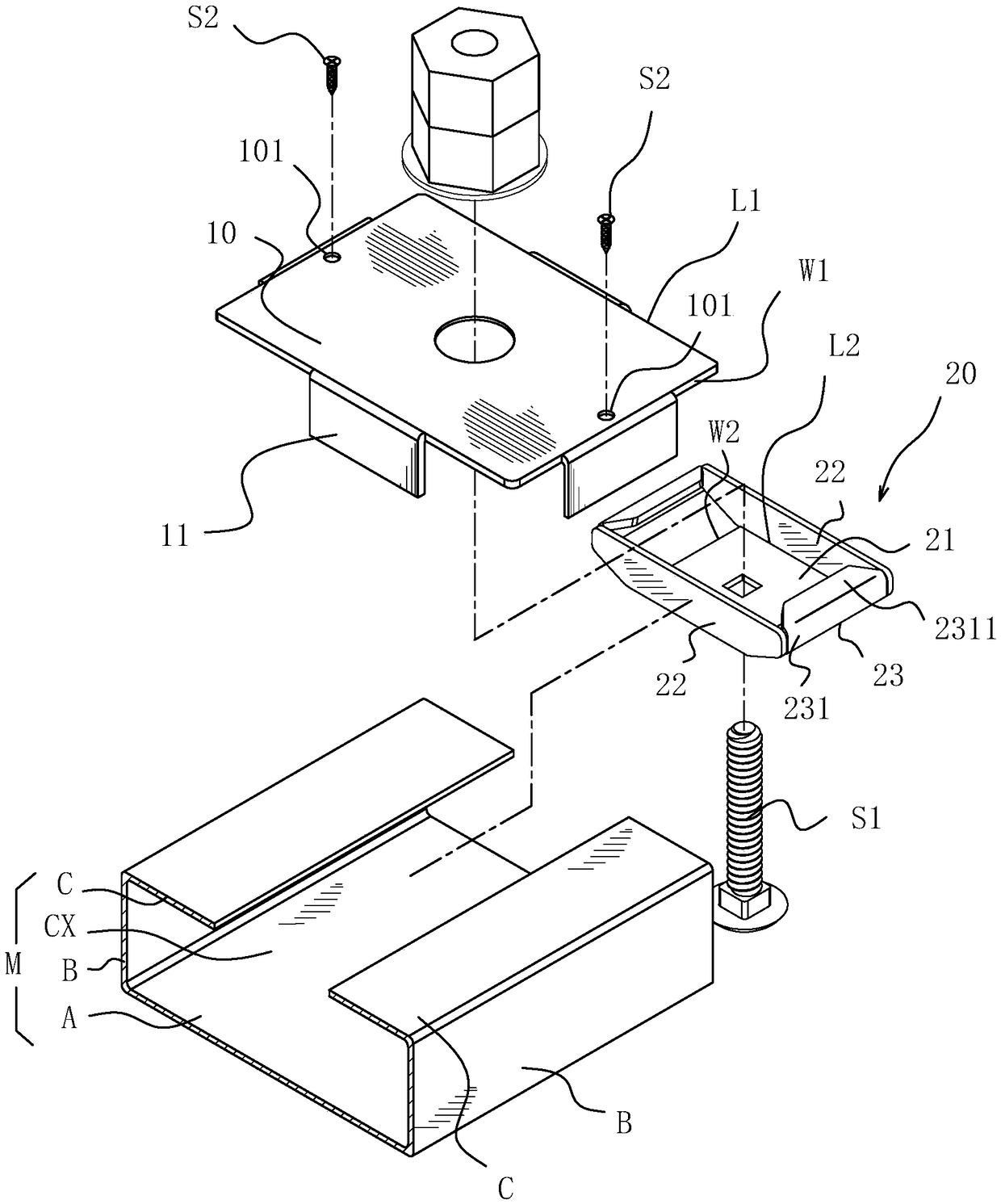
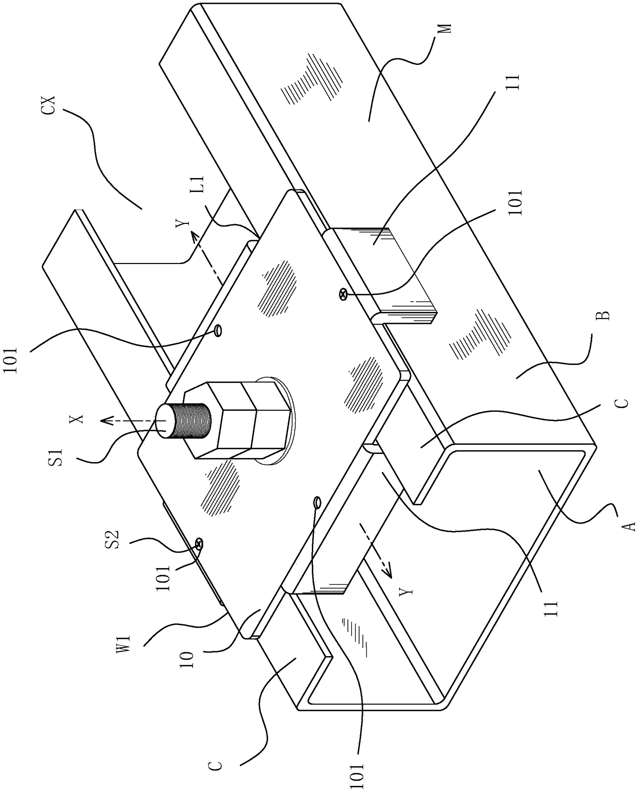
[0041] see Figure 1 to Figure 3 as shown, figure 1 It is a three-dimensional exploded schematic diagram of the first embodiment of the high-strength bracket combined structure of the present invention, showing that the short-side opening sleeve of the locking cover is correspondingly inserted into the opening side of the C-shaped steel; figure 2 It is a three-dimensional exploded schematic diagram of the first embodiment of the high-strength bracket composite structure of the present invention, showing that the long-side opening sleeve of the locking cover is correspondingly inserted into the opening side of the C-shaped steel; image 3 It is a three-dimensional assembly diagram of the first embodiment of the high-strength bracket assembl...


PUM


Abstract

The present invention discloses a highly versatile and easy-to-assemble high-strength support assembly structure, which utilizes a fastening cover part that can be slidably sleeved onto a C-type steeland an opening side thereof and a flexible internal stand; the flexible internal stand is placed inside of the C-type steel, and the internal stand and the fastening cover part are correspondingly fastened at the opening side of the C-type steel, such that the opening side of the C-type steel can serve as a connecting end or a bearing side. The present invention also discloses using or stacking asingle or a plurality of connecting plates, so as to allow one C-type steel to be correspondingly joined to another C-type steel in order to expand a length thereof, or to adapt the C-type steel forserving as a corner, thereby realizing the highly versatile and easy-to-assemble high-strength support assembly structure.

Description

technical field [0001] The present invention relates to a bracket combination structure, in particular to a high-strength bracket combination structure with high strength (not easy to deform), high versatility and simple (fast) assembly characteristics. . Background technique [0002] Common support structures, whether used as supporting solar panel supports, greenhouse agricultural shed supports, parking shed supports or even furniture skeletons, are mostly made of steel as beams and longitudinal beams L overlap each other to form a three-dimensional rectangular support (such as Figure 15 shown). [0003] The types of steel used as brackets in the industry are divided into C-shaped steel, square (round) pipe, or H-shaped steel according to their cross-sectional shapes. C-shaped steel is the most commonly used bracket for today because of its high strength, corrosion resistance, easy processing and production, and low cost. types of steel. [0004] It is observed that the...

Claims


Application Information

Patent Timeline
Patent Type & Authority Applications(China)
IPC IPC(8): F16B7/18
CPCF16B7/187F24S2025/804F24S25/30F24S25/65F24S2025/6006H02S20/00E04B2001/2415C22C38/00F24S25/13Y02E10/50Y02E10/47Y02B10/10H02S20/23F24S25/00
Inventor 戴沛琳
Owner 尚稚程
Why Eureka
Try Eureka