Method for automatically splicing scribing groove frame

An automatic splicing and dicing groove technology, which is applied in special data processing applications, instruments, electrical digital data processing, etc., can solve the problems of time-consuming manual processing, error-prone, wafer scrapping, etc., and achieve the effect of automatic splicing

Inactive Publication Date: 2018-10-09
SHANGHAI HUAHONG GRACE SEMICON MFG CORP
View PDF8 Cites 2 Cited by
  • Summary
  • Abstract
  • Description
  • Claims
  • Application Information

AI Technical Summary

Problems solved by technology

For the complex process of converting α data into β data, on the one hand, manual processing takes a long time; (wafer) scrapping and other direct economic losses
The probability of human error is high, which brings great risks to product manufacturing

Method used


Image

  • Method for automatically splicing scribing groove frame

Examples


Embodiment Construction

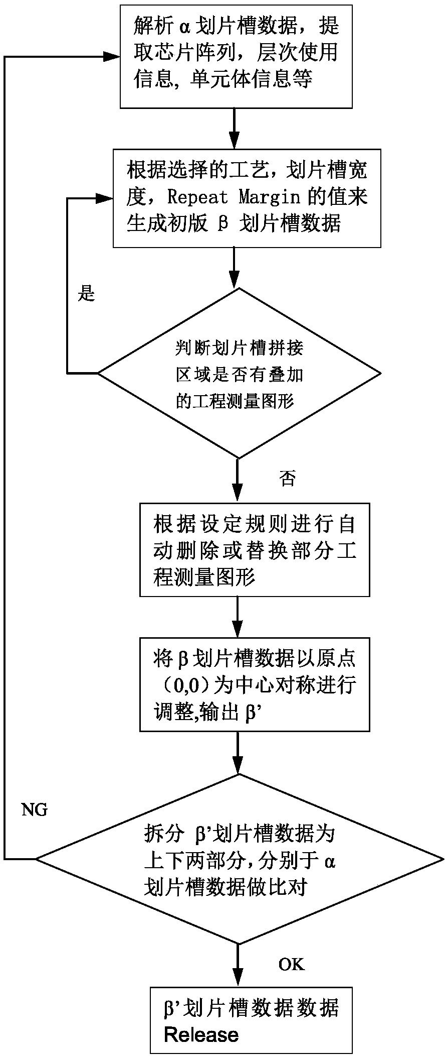
[0016] The method for realizing the automatic splicing of the scribe groove frame of the present invention is as follows: figure 1 shown, including the following steps:

[0017] Step 1: Analyzing the α-scribing groove data, extracting the chip array, layer usage information, unit body information, etc.

[0018] Due to the maximum exposure size of the 5X mask (X p ×Y p ) is 22mm×22mm, the maximum exposure size of 5X mask (X p ×Y p ) is 25mm×33mm. The width of the scribe groove is 50um / 60um / 80um optional. According to the size of the Main chip (CX: X-direction size of the customer's main chip; CY: Y-direction size of the customer's main chip) and the width of the dicing groove (SW), the value of the overlapping margin (RM), the number of chips in the horizontal direction (AX), the vertical number of chips (AY), calculate the 5X Frame Shot Size (α scribe groove exposure size):

[0019] The maximum exposure size in X direction MX=(CX+SW)×AX+2×RM (requires MX<22mm)

[0020]...


PUM


Abstract

The invention discloses a method for automatically splicing a scribing groove frame. A chip array is determined by directly reading layout data of a scribing groove and extracting a chip identification layer, afterwards, by calculating set values like the width of the scribing groove and repeat margin, the scribing groove frame is automatically spliced, and it is ensured that engineering surveyinggraphs in a splicing region cannot mutually interfere due to overlapping.

Description

technical field [0001] The invention relates to the field of integrated circuit manufacturing, in particular to a method for realizing automatic splicing of scribe groove frames. Background technique [0002] In the mask design process, in order to improve the exposure efficiency of lithography, the mass products of some processes have special requirements for the design of the scribe groove, that is, after generating an Array (array) = 1*1 data α, it must be based on the data Generate an Array=1*2 β data. For the complex process of converting α data into β data, on the one hand, manual processing takes a long time; (wafer) scrapping and other direct economic losses. The probability of human error is high, which brings great risks to product manufacturing. Contents of the invention [0003] The purpose of the present invention is to provide a method for splicing scribe groove frames, realize automatic splicing of scribe groove frames, and ensure that the engineering mea...

Claims


Application Information

Patent Timeline
Patent Type & Authority Applications(China)
IPC IPC(8): G06F17/50
CPCG06F30/39
Inventor 张燕荣张兴洲
Owner SHANGHAI HUAHONG GRACE SEMICON MFG CORP
Why Eureka
Try Eureka