Input voltage feedforward apparatus and method
A technology of input voltage and output voltage, which is used in output power conversion devices, DC power input conversion to DC power output, electrical components and other directions, can solve the problem of difficulty in implementing input voltage feedforward, and achieve the effect of reducing overshoot voltage.
- Summary
- Abstract
- Description
- Claims
- Application Information
AI Technical Summary
Problems solved by technology
Method used
Image

Examples
specific Embodiment 1
[0059] Figure 4 It is a circuit principle block diagram of BUCK+full-bridge two-stage transformation topology input voltage feedforward according to an embodiment of the present invention, as Figure 4 As shown, how this specific embodiment implements input voltage feed-forward will be described in detail below.
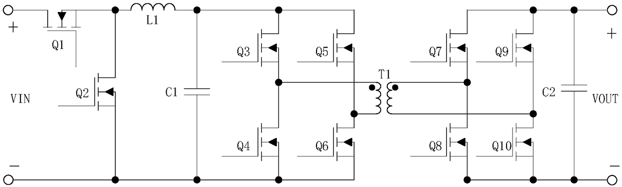
[0060] First, let me introduce the working principle of BUCK+ original side full bridge. Such as figure 1 As shown, this topology is the cascading of the first-stage BUCK transformation and the second-stage full-bridge transformation. The input of the full-bridge transformation is the output of the BUCK transformation, and the output rectification adopts full-bridge synchronous rectification. Among them, the second-stage full-bridge conversion works in an open-loop state, and its primary-side main-control drive duty cycle is about 0.48 (it should be noted that this duty cycle can be fine-tuned, and 0.48 is a preferred duty cycle), Therefore, the output filter ind...
specific Embodiment 2
[0066] Figure 7 It is a circuit principle block diagram of BOOST+full bridge two-stage transformation topology input voltage feedforward according to an embodiment of the present invention, as Figure 7 As shown, how this embodiment implements input voltage feed-forward will be described in detail below.
[0067] First, let me introduce the working principle of BOOST+ primary side full bridge whose output adopts full bridge synchronous rectification. Figure 8 It is the main circuit diagram of the BOOST+full bridge two-stage topology according to the embodiment of the present invention, such as Figure 8 As shown, this topology is the cascade of the first-stage BOOST transformation and the second-stage full-bridge transformation, and the input of the full-bridge transformation is the output of the BOOST transformation. Among them, the second-stage full-bridge conversion works in an open-loop state, and the duty cycle of the primary-side main driver is about 0.48, so the out...
specific Embodiment 3
[0073] Figure 11 It is a circuit schematic diagram (2) of BUCK+full bridge two-stage conversion topology input voltage feedforward according to an embodiment of the present invention, as Figure 11 As shown, the difference from the first embodiment is that the third embodiment is applied to the output of the BUCK+full bridge two-stage conversion topology using full-wave synchronous rectification, and the implementation method of input voltage feedforward is the same as that of the first embodiment The method is the same.
PUM
 Abstract
Description
Claims
Application Information
 - R&D
- Intellectual Property
- Life Sciences
- Materials
- Tech Scout
- Unparalleled Data Quality
- Higher Quality Content
- 60% Fewer Hallucinations
Browse by: Latest US Patents, China's latest patents, Technical Efficacy Thesaurus, Application Domain, Technology Topic, Popular Technical Reports.
© 2025 PatSnap. All rights reserved.Legal|Privacy policy|Modern Slavery Act Transparency Statement|Sitemap|About US| Contact US: help@patsnap.com