
Automatic assembling system for rotor parts of rotary machine

A technology of rotating machinery and automatic assembly, applied in metal processing, metal processing equipment, manufacturing tools, etc., can solve the problems of difficulty in ensuring assembly quality, inability to precisely control torque and angle, and inability to adjust tightening sequence.

Inactive Publication Date: 2018-10-12
DALIAN UNIV OF TECH
View PDF6 Cites 3 Cited by
  • Summary
  • Abstract
  • Description
  • Claims
  • Application Information

AI Technical Summary

Problems solved by technology

Its disadvantages: no precise control and recording of applied torque and angle, and no possibility to adjust the tightening sequence
Its disadvantage is that it is impossible to store multiple processing positions for automatic processing, and it is also impossible to adjust the tightening sequence
Its shortcoming is: can't realize automatic tightening
[0010] The prior art discloses an automatic bolt tightening machine, which includes a base, a frame mounted on the base, a rotary positioning assembly, a tightening assembly and a workpiece clamping assembly, the rotary positioning assembly is installed on the base, and the rotary positioning assembly includes a lifting table and The first lifting cylinder, the lifting table is equipped with a rotating cylinder, a rotating table, a bearing seat, a cushion block and a positioning round pin, and the rotating cylinder drives the rotating table to rotate; the tightening assembly is installed on the frame, and the tightening assembly includes the second lifting cylinder , The first linear guide rail and the lifting slide table, the lifting slide table is equipped with a mounting seat, a translation cylinder, a second linear guide rail and a vertical mounting platform, the second linear guide rail is installed on the mounting seat, and the translation cylinder passes through the second linear guide rail Drive the vertical installation platform to move horizontally. The vertical installation platform is equipped with a fixed seat, a servo tightening wrench, a contact sensor, a guide shaft and a limit bolt. The disadvantage is that the output torque cannot be accurately controlled and recorded.
[0011] The current assembly and tightening process of rotating machinery rotor parts has the following deficiencies: for the bolt group connection, the planning of the assembly and tightening process mainly relies on manual operation, and the assembly quality is difficult to be guaranteed; Coaxial disk size, different tightening parameters (tightening control method, torque, angle, speed, tightening sequence, number of tightening steps, tightening degree per step) automatic assembly test bench

Method used


Image

  • Automatic assembling system for rotor parts of rotary machine
  • Automatic assembling system for rotor parts of rotary machine
  • Automatic assembling system for rotor parts of rotary machine

Examples


Embodiment Construction

[0026] In order to make the purpose, technical solutions and advantages of the embodiments of the present invention clearer, the technical solutions in the embodiments of the present invention will be clearly and completely described below in conjunction with the drawings in the embodiments of the present invention. Obviously, the described embodiments It is a part of embodiments of the present invention, but not all embodiments. Based on the embodiments of the present invention, all other embodiments obtained by persons of ordinary skill in the art without making creative efforts belong to the protection scope of the present invention.

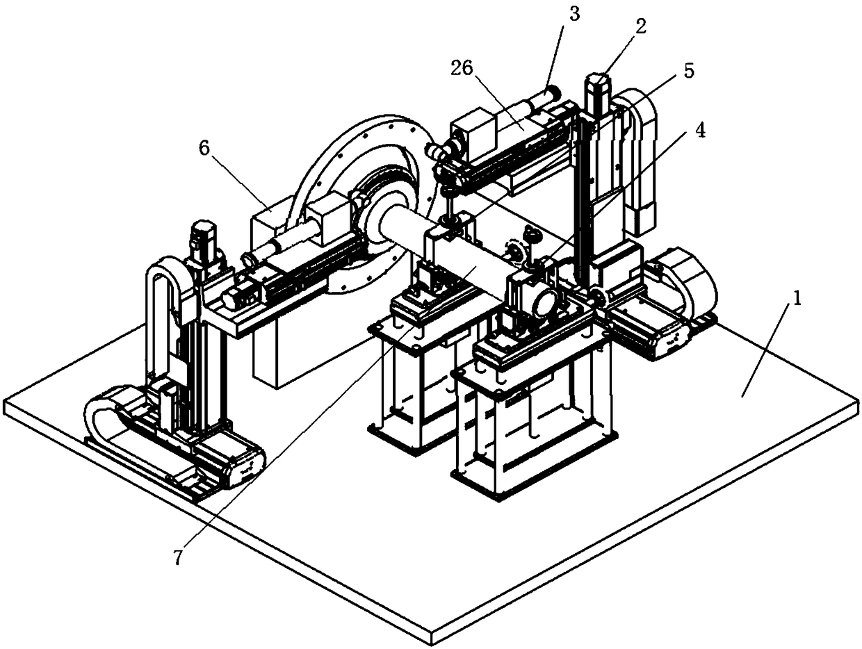
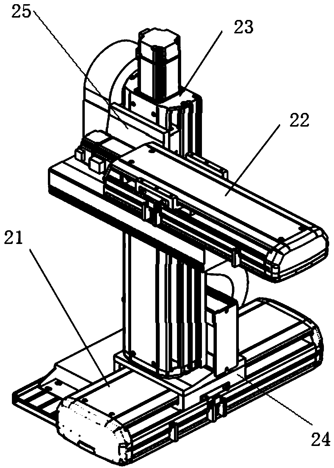
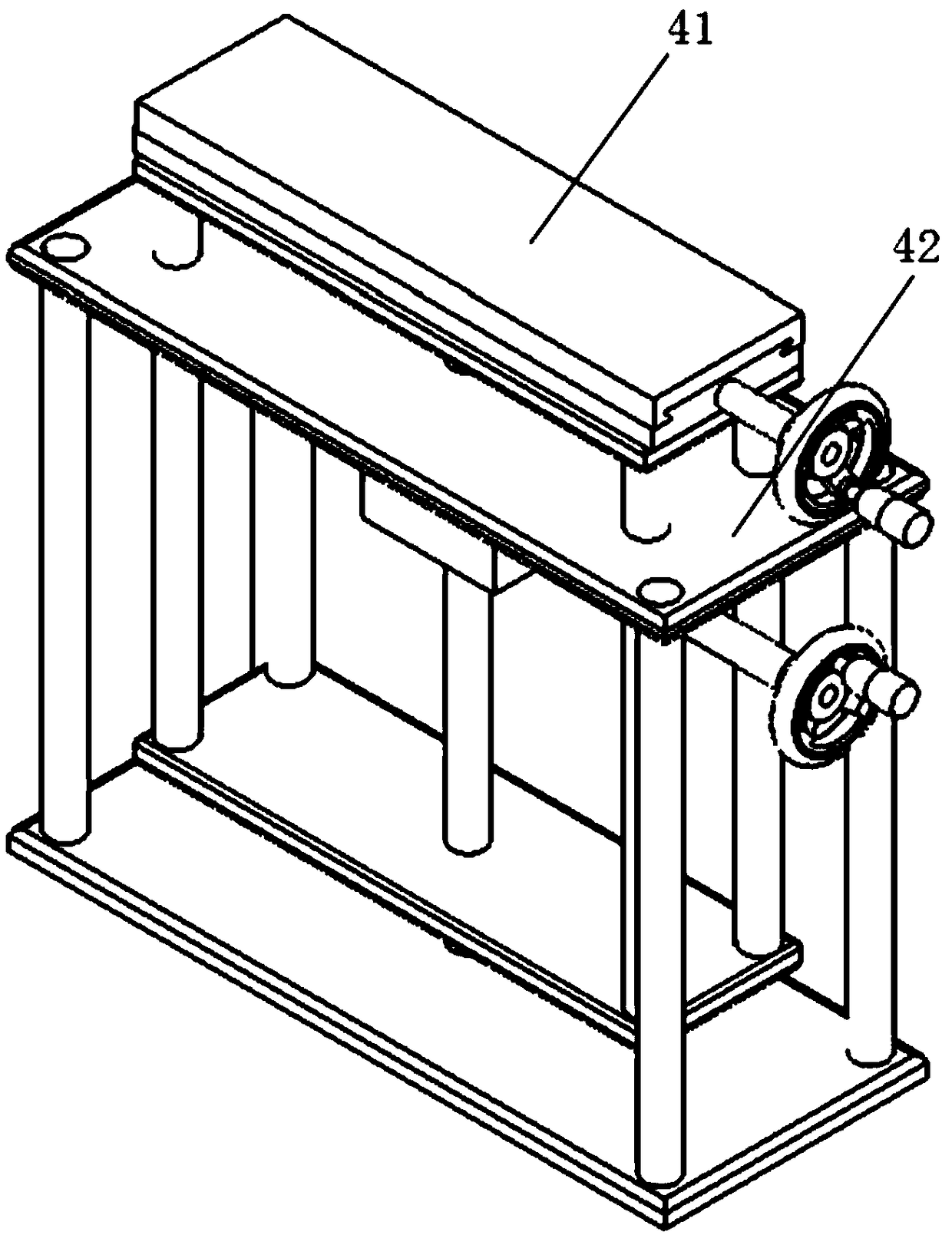
[0027] Such as Figure 1-Figure 3 As shown, an automatic assembly system for rotating mechanical rotor parts includes a base 1, and two Cartesian coordinate system robots 2 arranged symmetrically in a mirror. The Cartesian coordinate system robots 2 include X-axis slide rails 21 and Y-axis slide rails 22. And the Z-axis slide rail 23, the X-...


PUM


Abstract

The invention discloses an automatic assembling system for rotor parts of a rotary machine. The system comprises a base station and two rectangular coordinate system robots which are arranged in mirror symmetry. Each of the rectangular coordinate system robots comprises an X-axis slide rail, a Y-axis slide rail and a Z-axis slide rail, wherein the X-axis slide rail is fixedly connected to the upper surface of the base station, the lower end of the Z-axis slide rail is slidably connected to the X-axis slide rail through a Z-axis slide block, the side wall of one side of the Y-axis slide rail isslidably connected to the Z-axis slide rail through a Y-axis slide block, and the Y-axis slide rail is connected to an electric tightening shaft through an electric tightening shaft slide block. Theautomatic assembling system for the rotor parts of the rotary machine also comprises a first n-shaped clamp, a second n-shaped clamp and a third n-shaped clamp which are successively arranged along the direction of axis of symmetry of the two rectangular coordinate system robots. The system disclosed by the invention can tighten bolts according to different specifications of bolts, different reeldimensions, different tightening parameters and the like, and controls the bolt tightening process precisely.

Description

technical field [0001] The invention belongs to the field of bolt assembly and relates to an automatic assembly system for rotor parts of rotating machinery. Background technique [0002] The connection structure of rotating mechanical rotor parts uses a large number of fastening bolts. In the actual assembly process, aero-engine failures caused by unreasonable bolt assembly processes occur from time to time. Therefore, the quality control requirements for bolt connection assembly during assembly are very high high. Since the main assembly work of the bolted joint is the bolt tightening operation, the equipment and process of bolt tightening play a key decisive role. [0003] In the assembly process of the connecting structure of the rotating machinery rotor parts, manual operations are basically used, so the assembly quality is greatly affected by human factors, and the consistency of assembly and manufacturing is not ideal. In terms of the fastening process of the thread...

Claims


Application Information

Patent Timeline
Patent Type & Authority Applications(China)
IPC IPC(8): B23P19/06
Inventor 孙伟张博超马跃孙清超韩清凯张伟
Owner DALIAN UNIV OF TECH
Learn More