

Mechanical feeding mechanism and using method
A mechanical feeding and feeding technology, applied in the field of mechanical feeding mechanism, can solve the problems of low adaptability, low degree of automation, complex structure, etc., and achieve the effects of low production and operation and maintenance costs, simple structure and wide application range.
- Summary
- Abstract
- Description
- Claims
- Application Information
AI Technical Summary
Problems solved by technology
Method used
Image

Examples
Embodiment Construction
[0021] Embodiments of the present invention will be further described below in conjunction with the accompanying drawings.
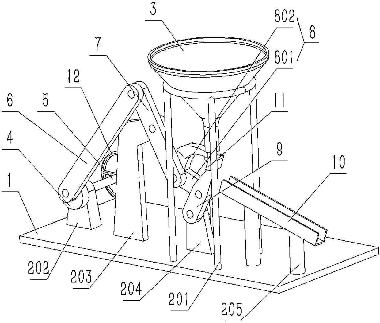
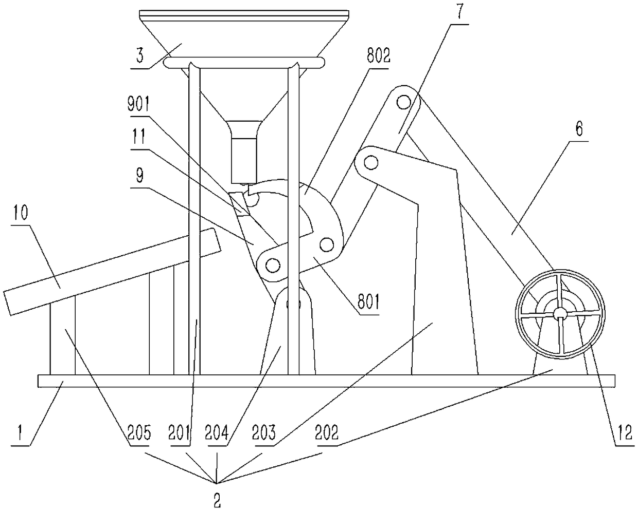
[0022] Please see attached figure 1 and attached figure 2 As shown, a mechanical feeding mechanism includes a base 1, a bracket 2, a funnel 3, a cam 4, a handle 5, a first connecting rod 6, a second connecting rod 7, a third connecting rod 8, a fourth connecting rod 9 and feeding Groove 10; The base 1 is a rectangular body structure; The support 2 includes a funnel support 201, a driving support 202, an intermediate support 203, a working support 204 and a feeding support 205; and the described funnel support 201, driving support 202 , the middle bracket 203, the working bracket 204 and the feeding bracket 205 are fixed on the top surface of the base 1 by welding; the funnel 3 is fixed on the funnel bracket 201; the handle 5 is arranged on the on the drive bracket 202, and can rotate along its own axis; the middle part of the second connecting rod 7 i...
PUM
 Abstract
Description
Claims
Application Information