High-temperature pellet cooling device

A technology of cooling devices and pellets, which is applied in the field of metallurgical equipment, can solve problems such as energy waste, and achieve the effects of avoiding large energy consumption, eliminating unorganized steam emissions and deposition, and preventing internal deposition and bonding

Active Publication Date: 2018-10-12
CHONGQING CISDI THERMAL & ENVIRONMENTAL ENG CO LTD +1
View PDF9 Cites 0 Cited by
  • Summary
  • Abstract
  • Description
  • Claims
  • Application Information

AI Technical Summary

Problems solved by technology

[0003] In view of this, the object of the present invention is to provide a high-temperature pellet cooling device to solve the energy waste problem existing in the existing cooling methods

Method used


Image

  • High-temperature pellet cooling device

Examples


Embodiment Construction

[0021] The preferred embodiments of the present invention will be described in detail below with reference to the accompanying drawings.

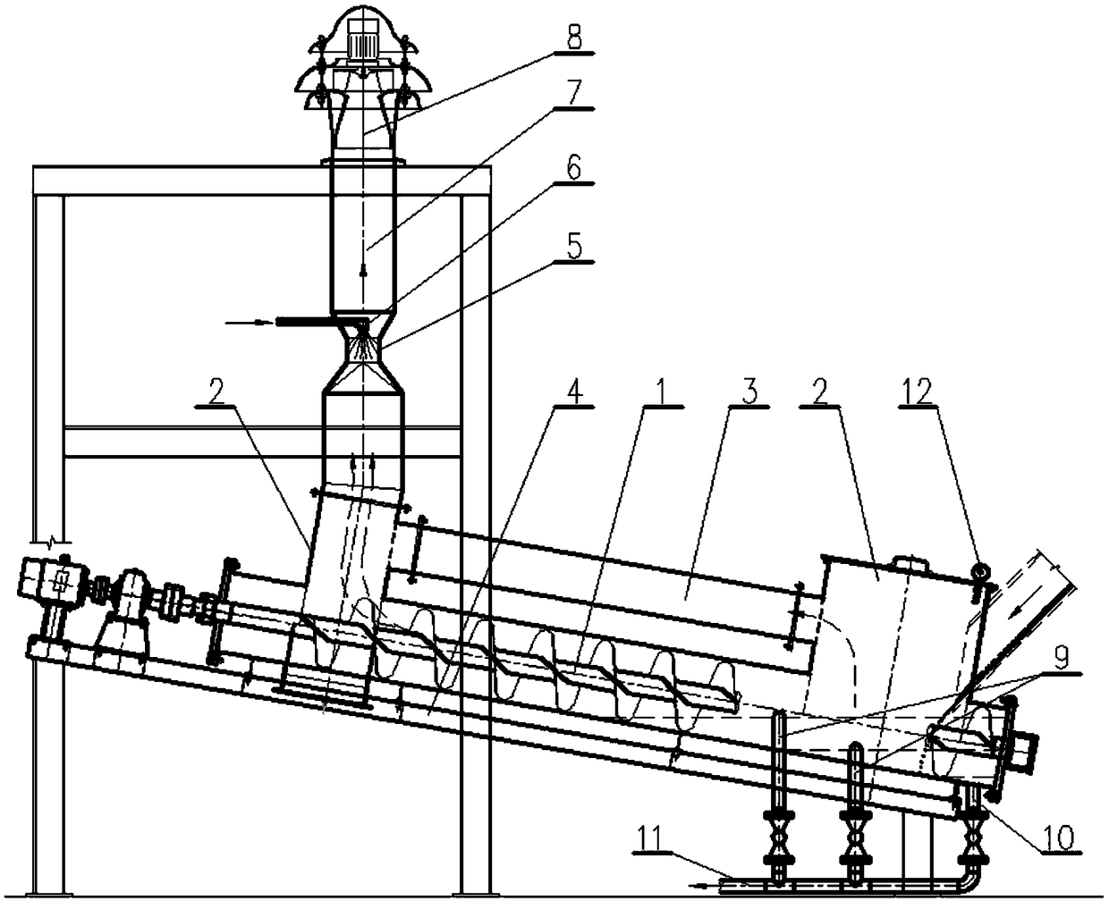
[0022] As shown in the figure, the high-temperature pellet cooling device in the present invention includes a screw discharge device 1, and the feed end of the screw discharge device 1 is provided with a water tank, which is arranged obliquely on the machine in such a way that the discharge end is higher than the feed end. On the frame 4; also includes a steam cooling device, the steam cooling device is not only connected with the gas collecting hood 2 at the inlet and outlet ends of the screw discharge device 1 through the communication pipe 3, but also communicated with the atmosphere. After the high-temperature pellets are quenched and cooled by the spiral discharge device, they are taken out and drained, and discharged through the discharge port. The steam generated during the water quenching process is sent to the steam cooling device t...


PUM


Abstract

The invention discloses a high-temperature pellet cooling device which comprises a spiral discharging device,a steam cooling device and a water discharging device. The problems of high-temperature pellet cooling,discharging and steam recovery are systematically solved,the problems of high energy consumption and likely pellet breakage of an indirect cooling mode are avoided,and the problems of inorganized steam discharging and silting caused by a slag basin water quenching mode are also eliminated. The high-temperature pellet cooling device is simple and easy to control,high in production efficiency and wide in application prospect.

Description

technical field [0001] The invention belongs to the field of metallurgical equipment, and in particular relates to a high-temperature pellet cooling device. Background technique [0002] The cooling of high-temperature pellets is extremely important to the subsequent processing and utilization of pellets. When high-temperature pellets need crushing and magnetic separation, the indirect cooling method not only consumes a lot of resources such as water and nitrogen, but also has relatively high pellet strength, which will give crushing magnetism. The selection brings difficulties. If the slag pond water quenching cooling method is adopted, on the one hand, a large amount of steam will be discharged unorganized, wasting water resources, and on the other hand, it will cause siltation in the slag pond, resulting in difficulty in discharging materials and unsustainable production. . Contents of the invention [0003] In view of this, the object of the present invention is to pr...

Claims


Application Information

Patent Timeline
Patent Type & Authority Applications(China)
IPC IPC(8): C22B1/26
CPCC22B1/26
Inventor 郭秀键田文杰罗宝龙雍海泉
Owner CHONGQING CISDI THERMAL & ENVIRONMENTAL ENG CO LTD
Why Eureka
Try Eureka