
Laser cladding device for inner walls of medium-diameter and small-diameter pipelines

A laser cladding, small diameter technology, applied in the field of laser cladding equipment, can solve problems such as space constraints, achieve good quality, reduce the size and weight of the effect

Inactive Publication Date: 2018-10-12
JIANGSU UNIV
View PDF3 Cites 7 Cited by
  • Summary
  • Abstract
  • Description
  • Claims
  • Application Information

AI Technical Summary

Problems solved by technology

[0005] The purpose of the present invention is to overcome the deficiencies of the existing technology, to meet the actual needs, to provide a laser cladding device for the inner wall of medium and small diameter pipes, which solves the problem of limited space in the laser cladding of the inner wall of small and medium diameter pipes, and can realize the laser cladding device with a diameter of 200mm. Spiral Laser Cladding Processing of Inner Wall of Medium and Small Pipes

Method used


Image

  • Laser cladding device for inner walls of medium-diameter and small-diameter pipelines
  • Laser cladding device for inner walls of medium-diameter and small-diameter pipelines

Examples


Embodiment

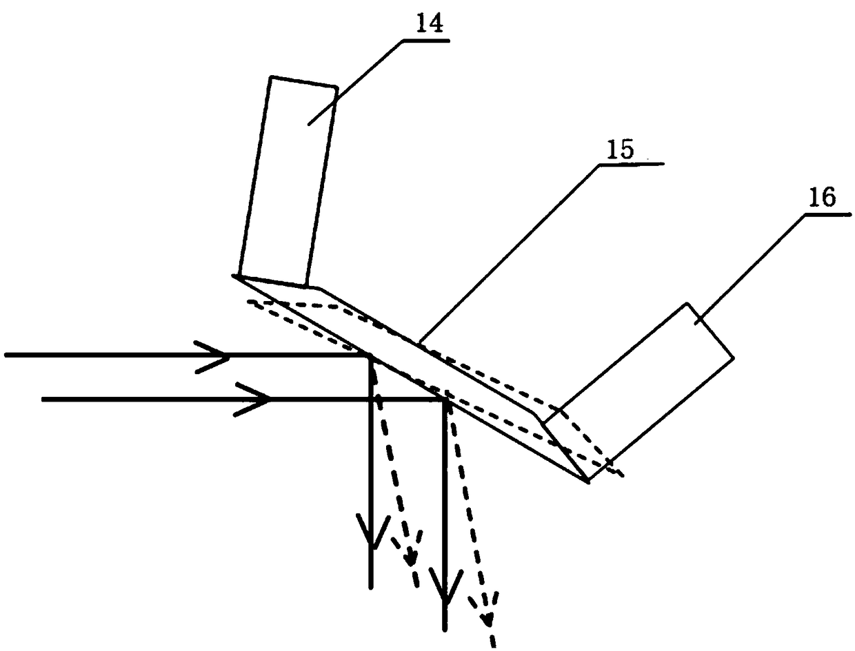
[0020] Use the present invention to the laser cladding device of domestic new-style SPCC cold-rolled carbon steel pipe inner wall diameter 200mm such as figure 1 As shown, it includes: an optical fiber connector 1, a cylinder body 6, a powder feeding nozzle 12, a cladding head 17, a fixing device and an adjusting device, wherein the fixing device includes a card seat 2, a connecting plate 5 and a connecting flange 4, and the cylinder body 6 includes Laser channel 8, powder feeding tube 9 and water-cooling tube 10, the laser channel 8 is provided with a collimating mirror 3, a protective mirror 7 and a focusing mirror 11 in sequence along the direction of laser advance, the optical fiber joint 1 is fixedly connected to the left end of the cylinder body 6, The card holder 2 is fixedly installed in the preset groove on the outer wall of the cylinder and fixed by bolts, the connecting plate 5 and the card holder 2 are fixedly connected by bolts, and the other end of the connecting ...


PUM


Abstract

The invention belongs to the technical field of laser cladding equipment, and particularly relates to a laser cladding device for inner walls of medium-diameter and small-diameter pipelines. The lasercladding device comprises an optical fiber connector, a cylinder, a powder feeding nozzle, a cladding head, a fixing device and an adjustment device, wherein the cylinder and a mechanical arm are connected through the fixing device. The cylinder comprises a laser channel, a powder feeding pipe and a water cooling pipe. A collimating lens, a protective lens and a focusing lens are sequentially arranged in the laser channel in the laser advancing direction. The optical fiber connector is fixedly connected with the left end of the cylinder. The adjustment device comprises a first small electrictelescopic rod machine fixedly arranged at the top end of the outer wall of the cladding head and a second small electric telescopic rod machine fixedly arranged at the right end of the outer wall ofthe cladding head. Electric telescopic rods of the first small electric telescopic rod machine and the second small electric telescopic rod machine stretch into the cladding head separately from the outer walls of the top end and the right end of the cladding head to be connected with the two ends of a reflector, and the reflector is made to rotate by controlling the two telescopic rods. The powder feeding nozzle is fixedly mounted at the bottom end of the outer wall of the cladding head. By adoption of the laser cladding device, the problem that laser cladding of the inner walls of the medium-diameter and small-diameter pipelines is limited by the space is solved.

Description

technical field [0001] The invention belongs to the field of laser cladding equipment, in particular to a laser cladding device for the inner wall of medium and small diameter pipelines. Background technique [0002] In shipbuilding, petroleum, mining and other manufacturing industries, a large number of pipes are required. The inner walls of these pipes will be worn to varying degrees during use, which will affect their performance and life. Therefore, the wear resistance and corrosion resistance of the inner walls of the pipes will be increased. Performance is key to solving this problem. [0003] As a new technology for surface modification of materials, laser cladding technology refers to placing selected coating materials on the surface of the coated substrate with different fillers, and melting them and the surface layer of the substrate at the same time through laser irradiation, and quickly After solidification, the diluted layer base is formed and the surface coati...

Claims


Application Information

Patent Timeline
IPC IPC(8): C23C24/10
CPCC23C24/10
Inventor 罗开玉周阳
Owner JIANGSU UNIV
Learn More