
Laser top-surface cladding method

A top surface and laser technology, applied in metal material coating process, coating, etc., can solve the problems of no visibility, difficulty of top surface cladding, etc., to achieve no energy loss, avoid damage to the protective mirror, and strong usability Effect

Active Publication Date: 2012-07-11
上海大陆天瑞激光表面工程有限公司
View PDF0 Cites 0 Cited by
  • Summary
  • Abstract
  • Description
  • Claims
  • Application Information

AI Technical Summary

Problems solved by technology

[0004] At present, due to the limitation of laser and optical path transmission, the existing laser cladding method can only carry out laser cladding on the facade and plane, and there is still a certain difficulty in cladding the top surface.
[0005] According to the applicant's search and verification: there is no domestic precedent for repairing or anti-corrosion of equipment components using laser top surface cladding technology, and no relevant reports have been seen abroad

Method used


Image

  • Laser top-surface cladding method
  • Laser top-surface cladding method

Examples


Embodiment Construction

[0016] Now in conjunction with the accompanying drawings and embodiments, the technical solution of the present invention is further introduced.

[0017] The anti-corrosion treatment process steps of a PTA exhaust pipe are as follows:

[0018] 1. Detect and record before cladding.

[0019] 2. Grind the cladding surface before cladding to clean up the corrosion layer.

[0020] 3. Laser cladding:

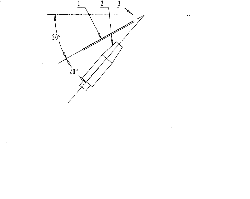
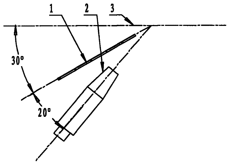
[0021] a) Before cladding, adjust the angle between the laser powder feeding head 1 and the laser processing head 2. As shown in the figure, when the laser top surface is cladding, the laser processing head 2 and the processed surface cannot be perpendicular to each other, and there must be a certain angle. Prevent the metal powder from entering the laser processing head 2. Metal powder entering the laser processing head 2 may cause damage to the protective mirror of the laser processing head 2. The laser processing head 2 and the top surface 3 are at 50°, and the clamp between the ...


PUM


Abstract

The invention relates to a laser top-surface cladding method, which is characterized in that when carrying out laser top-surface cladding, an included angle is formed by a laser processing head and a processed surface so as to prevent metal powders from entering the laser processing head, wherein an included angle formed between by the laser processing head and a top surface is 48-52 degrees, andan included angle formed by a laser powder-conveying head and the top surface is 28-32 degrees; a pneumatic powder-conveying mode is adopted for conveying powders; a mechanical processing device controlled by a computer is adopted to guarantee smooth conduction of the laser top-surface cladding; a high-power laser is adopted and optical fiber conduction is utilized so as to reduce energy loss in the transmission process of laser; the top-surface cladding parameters are as follows: the diameter of a molten pool is 1-4mm, the depth of the molten pool is 0.05-0.5mm, the heating time is 0.001-0.1s, the laser power is 1000-5000w, the powder-conveying amount is 8-40g / min, the thickness of a cladding layer is 0.3-1.2mm, and the laser scanning speed is 6-15mm / s.

Description

Technical field: [0001] The invention relates to a laser cladding method, in particular to a laser top surface cladding method, which belongs to the technical field of C23C24 / 10 (2006.01) I in the IPC International Patent Classification Table. Background technique: [0002] As an advanced remanufacturing technology, laser cladding technology has been rapidly promoted and widely used in recent years. [0003] Laser cladding technology utilizes the characteristics of high energy concentration of high-energy laser beams to instantly completely melt alloy powders with special physical, chemical or mechanical properties that are preset on the surface of the substrate or automatically sent synchronously with the laser. It is partially melted to form a new composite material, which is rapidly solidified after laser beam scanning to obtain a dense coating that is metallurgically combined with the substrate to achieve the purpose of restoring geometric dimensions and surface strength...

Claims


Application Information

Patent Timeline
Patent Type & Authority Patents(China)
IPC IPC(8): C23C24/10
Inventor 付键伟刘豫陈江
Owner 上海大陆天瑞激光表面工程有限公司
Learn More