While-drilling direction sound wave imaging logging device

An imaging logging and azimuth technology, which is applied in measuring devices, seismology, and surveying for logging records, can solve problems such as difficulty in receiving acoustic signals and weak signal energy, and achieve the effect of improving the signal-to-noise ratio

Active Publication Date: 2018-10-12
INST OF GEOLOGY & GEOPHYSICS CHINESE ACAD OF SCI
View PDF13 Cites 7 Cited by
  • Summary
  • Abstract
  • Description
  • Claims
  • Application Information

AI Technical Summary

Problems solved by technology

However, since the monopole is used as a high-frequency signal and the quadrupole sound wave is a low-frequency signal, the same set of transducers is used to excite the sound wave signal. Due to the inherent frequency properties of the transducer, one signal energy is destined to be very weak. It is difficult for the receiving transducer to receive useful acoustic signals

Method used


Image

  • While-drilling direction sound wave imaging logging device
  • While-drilling direction sound wave imaging logging device
  • While-drilling direction sound wave imaging logging device

Examples


Embodiment 1

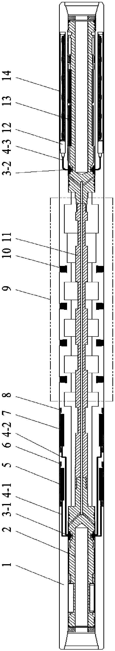
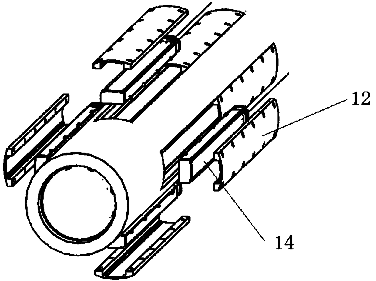
[0044] This embodiment provides an azimuth acoustic imaging logging device while drilling, such as figure 1 As shown, the device includes a drill collar 1, a transmitting transducer arranged on the drill collar 1 and a receiving transducer 12, and a transmitting transducer arranged between the transmitting transducer and the receiving transducer 12 Sound insulation 9.

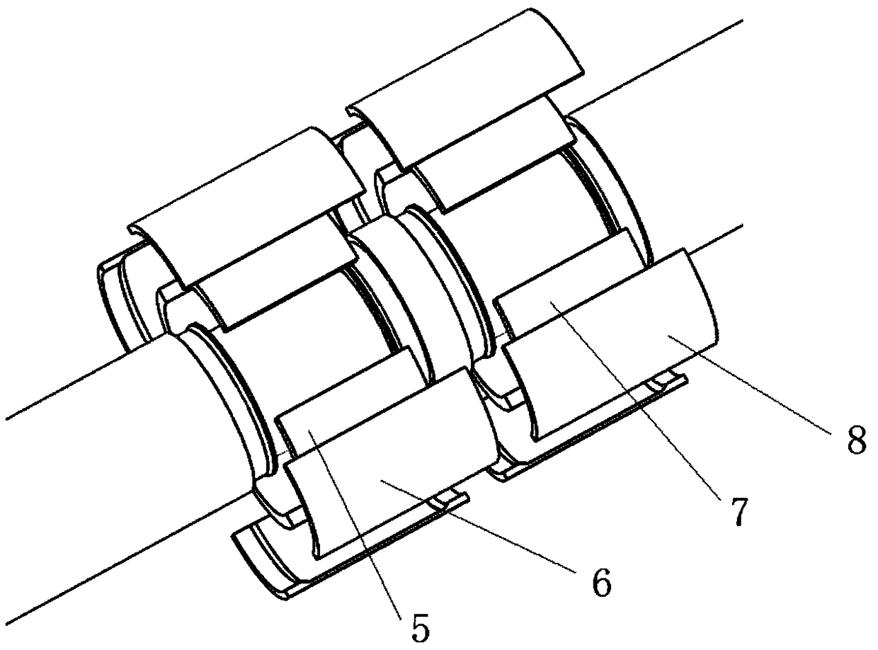
[0045] Described transmitting transducer comprises low-frequency transmitting transducer 5 and high-frequency transmitting transducer 7 two groups of transmitting transducers, is used for carrying out the excitation of multipole sub-mode wave, to improve emission energy;

[0046] The low-frequency transmitting transducer 5 adopts the dipole and quadrupole working modes, and the high-frequency transmitting transducer 7 adopts the monopole and partial pole working modes, and realizes the high-frequency transmitting state and the Separation of low-frequency emission states. Preferably, both the low-frequency tra...


PUM


Abstract

The invention mainly relates to the technical field of sound wave velocity measuring, in particular to a while-drilling direction sound wave imaging logging device which adopts two sets of transmitting transducers to conduct stimulation of multi-pole model waves. One set of the transmitting transducer is a high-frequency mono-pole and biased-pole transmitting transducer, and the other set is a low-frequency dipole and quadripole transmitting transducer. A high-frequency transmitting state and a low-frequency transmitting state are separated through a double-row transmitting scheme, and both the two sets of transmitting transducers can work at transducer resonance points through matched circuits, so that the transmitting energy is greatly improved. The working mode of the while-drilling direction sound wave imaging logging device comprises a mono-pole transmitting mode, a dipole transmitting mode, a quadripole transmitting mode and a biased-pole transmitting mode; the composite sound insulation mode of an inner engraved groove, inner variable diameters and a tungsten bar is adopted on the aspect of a sound insulator; signal receiving is achieved through the high-sensitivity transmitting transducers, and receiving of signals can be effectively achieved.

Description

technical field [0001] The invention mainly belongs to the technical field of acoustic wave velocity measurement, and in particular relates to an azimuth acoustic wave imaging logging device while drilling. Background technique [0002] With the continuous expansion of oil and gas field drilling scale and the development of science and technology. In particular, the rapid development of logging-while-drilling technology urgently requires the current advanced science and technology to play an important role in oil and gas field exploitation. Azimuth acoustic logging while drilling is one of the methods of logging while drilling. Acoustic logging while drilling realizes acoustic logging while drilling. Compared with wireline logging, the data obtained by acoustic logging while drilling is less affected by drilling fluid invasion, and can more effectively detect the lithology and physical properties of the wellbore formation and reservoir parameters. [0003] The velocity of...

Claims


Application Information

Patent Timeline
Patent Type & Authority Applications(China)
IPC IPC(8): E21B47/14E21B49/00
CPCE21B47/14E21B49/00G01V2001/526G01V1/52G01V1/44G01V2200/16
Inventor 郑健陈文轩底青云王自力孙云涛杨永友张文秀
Owner INST OF GEOLOGY & GEOPHYSICS CHINESE ACAD OF SCI
Why Eureka
Try Eureka