Supercharge Your Innovation With Domain-Expert AI Agents!

Assembled construction method of semi-backfilled shield cutter head maintenance well

A technology of shield cutter head and construction method, which is applied to shaft equipment, well sinking, filling and other directions, can solve the problems of low construction efficiency, narrow operation space, injury to operators, etc., so as to ensure construction safety and reduce The effect of backfilling workload and increasing construction speed

Active Publication Date: 2019-12-27
北京中地盾构工程技术研究院有限公司
View PDF6 Cites 0 Cited by
  • Summary
  • Abstract
  • Description
  • Claims
  • Application Information

AI Technical Summary

Problems solved by technology

However, in the current shield cutter head maintenance well, after excavation, the shaft wall adopts reinforced concrete structure, which will generate dust pollution during the construction process. It is very difficult to remove the concrete well wall from the ground, so it has to be left in the ground and backfilled with soil in the maintenance well. Cause adverse effects, not only poor environmental protection but also low construction efficiency
Moreover, in the construction of maintenance wells with concrete, especially in projects such as urban subways, due to the narrow operating space, complex operating environment, and various types of construction machinery, it is easy to cause injuries to operators and is subject to many nearby risk sources such as dense pipelines. impact, and it is not convenient for safe construction

Method used


Image

  • Assembled construction method of semi-backfilled shield cutter head maintenance well
  • Assembled construction method of semi-backfilled shield cutter head maintenance well
  • Assembled construction method of semi-backfilled shield cutter head maintenance well

Examples


Embodiment Construction

[0029] The technical solutions in the embodiments of the present invention will be clearly and completely described below in conjunction with the specific content of the present invention. Obviously, the described embodiments are only some of the embodiments of the present invention, not all of them. Based on the embodiments of the present invention, all other embodiments obtained by persons of ordinary skill in the art without making creative efforts belong to the protection scope of the present invention. The content not described in detail in the embodiments of the present invention belongs to the prior art known to those skilled in the art.

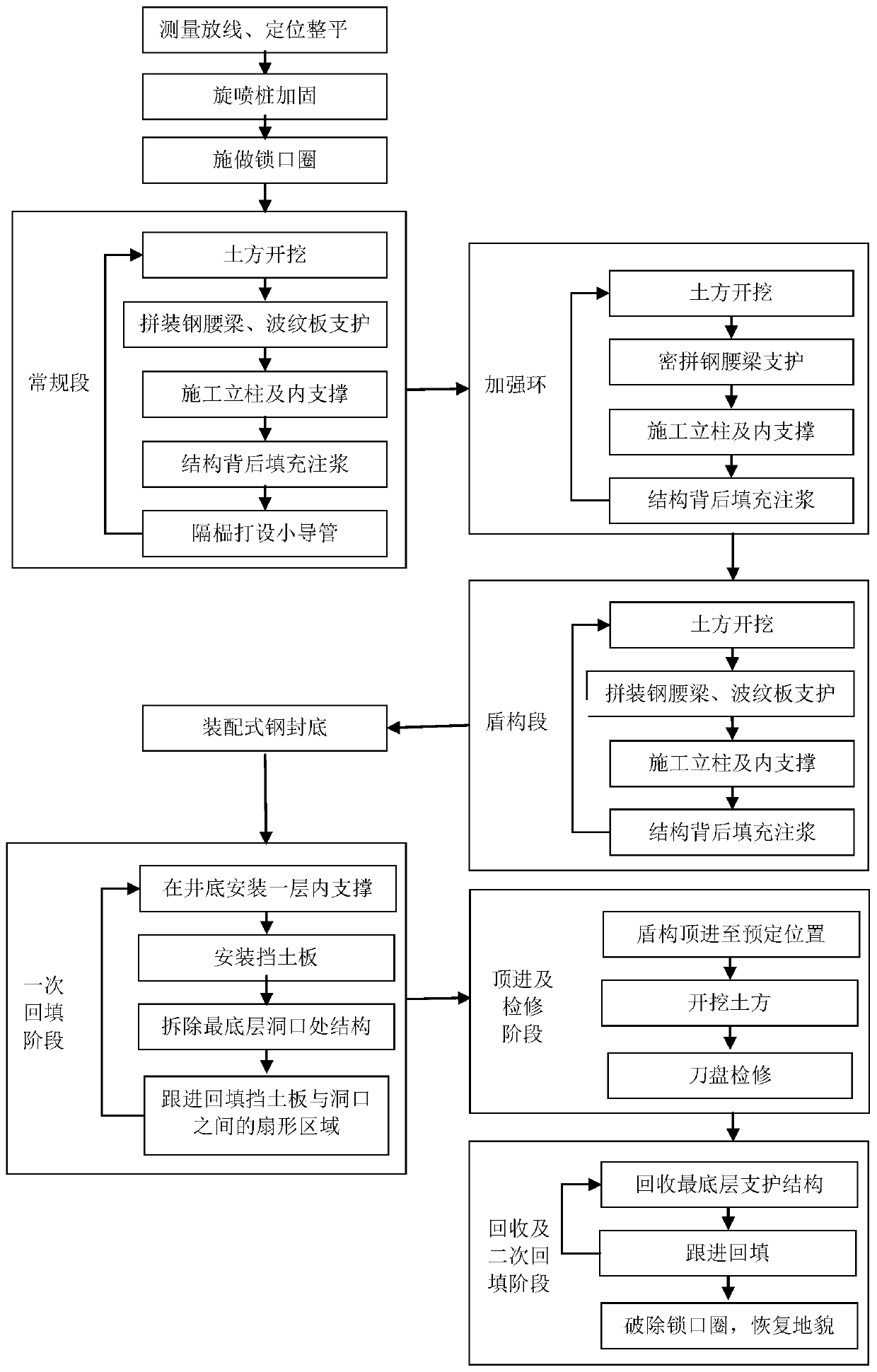
[0030] Such as figure 1 , 8 As shown, the embodiment of the present invention provides a semi-backfilled shield cutter head maintenance well assembly construction method, including:

[0031] Construction pretreatment is carried out at the position where the maintenance well is set; preferably, the pretreatment includes: leveling the...


PUM


Abstract

The invention discloses a shield cutterhead manhole assembly type construction method. The shield cutterhead manhole assembly type construction method comprises the steps that construction pretreatment is performed; an assembly type locking wellhead ring is manufactured at the excavation position of a manhole, and a wellhead guardrail is installed; the manhole is excavated in a layered mode, and an assembly type supporting structure is arranged in the manhole in a layered mode as the well wall support of the manhole, until the excavation is performed to the design depth, and a steel back coveris constructed at the bottom of the well in an assembling mode; a semi-backfilling method is adopted to remove the supporting structure at the opening to a first safe position above the top of a shield machine, and backfilling is performed to a second safe position of the top of the shield machine; and the shield machine enters a hole and excavates the earthwork to the bottom of the manhole to carry out the maintenance of a shield cutterhead, and the assembly type supporting structure in the manhole is dismantled in a layered mode after the maintenance of the shield cutterhead, the backfilling is followed up, and the shield machine continues to excavate after all the backfilling is completed. The shield cutterhead manhole assembly type construction method is high in safety and low in cost.

Description

technical field [0001] The invention relates to the field of maintenance well construction, in particular to an assembled construction method for a semi-backfilled shield cutter head maintenance well. Background technique [0002] In the current construction of tunnels and subways, shield tunneling technology is required. In the existing shield construction, it is necessary to overhaul the shield cutterhead during the construction process. Currently, to overhaul the shield cutterhead, it is necessary to set maintenance wells at intervals on the excavated route. However, in the current shield cutter head maintenance well, after excavation, the shaft wall adopts reinforced concrete structure, which will generate dust pollution during the construction process. It is very difficult to remove the concrete shaft wall from the ground, so it has to be left in the land and backfilled with soil in the maintenance well. Cause adverse effects, not only poor environmental protection an...

Claims


Application Information

Patent Timeline
Patent Type & Authority Patents(China)
IPC IPC(8): E21D1/08E21D5/00E21D5/06E21D8/00E21F15/00
CPCE21D1/08E21D5/00E21D5/06E21D8/00E21F15/00
Inventor 杨宇友
Owner 北京中地盾构工程技术研究院有限公司
Features
  • R&D
  • Intellectual Property
  • Life Sciences
  • Materials
  • Tech Scout
  • Unparalleled Data Quality
  • Higher Quality Content
  • 60% Fewer Hallucinations
Learn More